Welding Wire Size Calculator
Estimate a practical MIG or flux-core wire diameter from material thickness, process, amperage, transfer mode, deposition rate, wire feed speed, filler alloy, and weld position.
Choose a common weld setup. Each preset fills the calculator and runs the wire size estimate.
Wire Size Result
| Standard wire | Typical thickness | Solid wire amp range | Typical WFS | Common transfer mode |
|---|---|---|---|---|
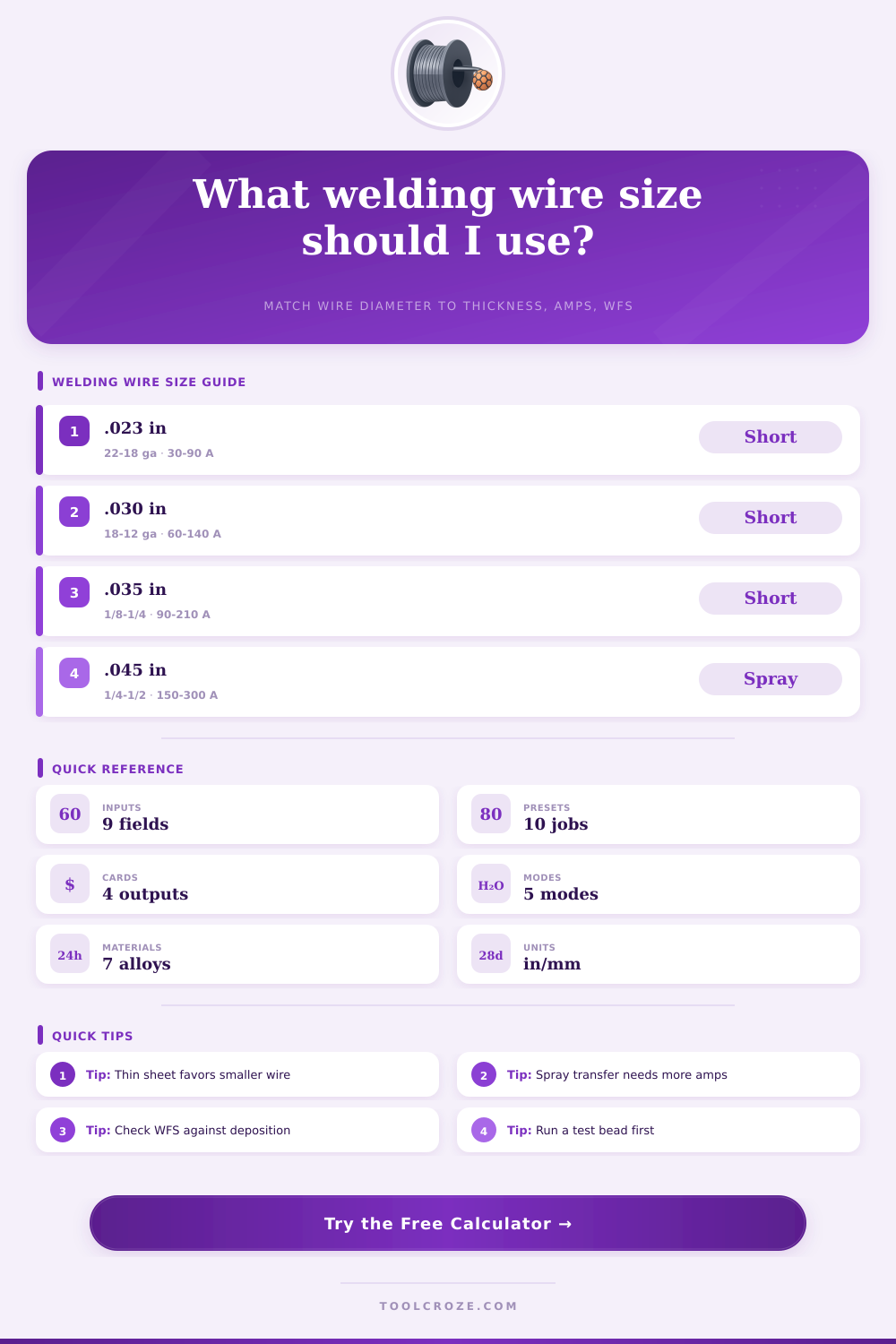
| 0.023 in / 0.6 mm | 24 ga to 16 ga | 30-90 A | 120-450 in/min | Short circuit sheet metal |
| 0.030 in / 0.8 mm | 20 ga to 1/8 in | 50-140 A | 140-450 in/min | Short circuit and light pulse |
| 0.035 in / 0.9 mm | 18 ga to 1/4 in | 80-210 A | 150-500 in/min | Short circuit, pulse, light spray |
| 0.040 in / 1.0 mm | 1/8 in to 5/16 in | 120-240 A | 160-450 in/min | Pulse and spray transfer |
| 0.045 in / 1.2 mm | 3/16 in to 1/2 in | 150-300 A | 130-420 in/min | Spray, pulse, flux core |
| 0.052 in / 1.4 mm | 1/4 in and thicker | 180-360 A | 110-330 in/min | Flux core structural welds |
| 1/16 in / 1.6 mm | 3/8 in and thicker | 250-450 A | 80-250 in/min | High deposition flux core |
| Process | Best wire sizes | Deposition behavior | Transfer notes |
|---|---|---|---|
| MIG solid wire | .023, .030, .035, .045 | Predictable WFS to metal rate | Short circuit for sheet, spray above threshold |
| FCAW-G flux core | .045, .052, 1/16 | High fill rate with slag coverage | Flat, horizontal, and position wires vary |
| FCAW-S flux core | .030, .035, .045, .068 | Outdoor-friendly with more spatter | Use listed polarity and stickout |
| Aluminum MIG | .030, .035, 3/64, 1/16 | Lower density needs faster WFS | Argon shielding and stable feeding matter |
| Metal-cored wire | .045, .052, 1/16 | High deposition with low slag | Often pulse or spray on plate work |
| Preset | Wire type | Thickness | Amps | Use case |
|---|---|---|---|---|
| Auto Sheet ER70S-6 .023 | Solid steel | 0.035 in | 55 A | Thin patch panels |
| Light Fabrication ER70S-6 .030 | Solid steel | 0.090 in | 110 A | Tube and brackets |
| Shop Fillet ER70S-6 .035 | Solid steel | 0.188 in | 165 A | General fillet welds |
| Spray Transfer ER70S-6 .045 | Solid steel | 0.375 in | 260 A | Flat plate welds |
| Dual Shield E71T-1 .045 | Flux core | 0.375 in | 240 A | Structural fillets |
| Aluminum ER5356 3/64 | Aluminum | 0.250 in | 210 A | Marine or trailer parts |
Another important factor to consider when choosing the correct wire diameters is the thickness of a metal that you are welding together. If the metal is particularly thin, you may want to use a wire that have a small diameter because you want to avoid applying too much heat to the metal. Conversely, if the metal is thick, you may want to use a wire that has a larger diameter to provide enough heat to adequate melt the thick metal.
Additionally, another factor to consider is your choice of transfer mode. Many welders often use short circuit transfer with thin metal because the short circuit transfer mode help to keep the heat level to the metal low. Spray transfer modes is used for thick metals because more metal can be transferred to the weld quick, but spray transfer mode is too aggressive to use for thin metals.
How to Choose the Right Wire Size for Welding
Finally, you could also use a calculator that determines the relationship between wire diameter and the rates at which the metal is deposited into the weld to ensure that you are not memorizing these settings. Wire feed speed is another factor that is used in the welding process. If you increase wire feed speed without increasing the voltage settings or the wire diameter, the welding process will be unstable.
Wire diameter and wire feed speed is related to one another because wire diameter will impact the amount of metal that is deposited into the weld. If you change wire diameter, the amount of metal deposited into the weld will change, even with the same wire feed speed. Therefore, if changes are made to wire diameter, the hour during which metal is deposited will change as well.
Additionally, another factor that will impact the welding process is the density of the metal. Metals like aluminum have different densities than metals like mild steel, and aluminum conducts heat more aggressive than mild steel. Because aluminum is less dense than mild steel, thin metal welds made with aluminum will require a faster wire feed speed to deposit the same amount of metal into the joint as mild steel welds will require.
The position in which the welder will perform the weld will also impact the wire diameter that is used in the welding process. Welding in thin metals in the flat welding position is more easier than welding in a vertical or overhead position. To combat the effects of gravity on thin metals in a vertical or overhead welding position, many welders will use a smaller diameter wire for the welding process.
By using a smaller diameter wire, the weld puddle will be smaller and easier to control, as well as be less likely to sag due to gravity. The amperage settings that you set up for the welding process also must be matched to the diameter of the wire that is used. Each wire diameter has a specific range of amperage settings within which the wire will efficiently weld the two pieces of metal together.
If you set the amperage that you select for use with a specific wire diameter to too high of a level, the weld arc will be unstable and there will be excessive spatter create during the welding process. If the amperage is too low for the selected wire diameter, there will be lack of fusion between the metal pieces that are being welded together. Lack of fusion will cause those two metals to fail if subjected to additional stress.
Two additional elements of the welding process that you should consider and set up correctly are the shielding gas that is used during the welding process and the polarity of the welding machine. The type of shielding gas will impact the type of transfer mode that is used during the welding process. For instance, you cannot achieve spray transfer mode if pure CO2 is used as the shielding gas.
Additionally, the shielding gas, wire diameter, and the amperage settings for the weld are all part of one system; if any of these element is incorrectly set up, the weld will be poor. It is important to use the estimates of the various settings as a starting point for the welding process. However, each welding machine is slightly different from each other welding machines, as are the environments in which the welds are performed.
Therefore, it is recommended that a welder performs a test weld on a scrap piece of the same material that will be welded together. Based off how the metal reacts to the test weld, you can adjust the wire feed speed and voltage. To find the correct wire diameter for the welding job, it is important to find a balance between the heat, the speed of the weld, and the amount of metal that is deposited into the weld joint.
If you match the wire diameter appropriately to the thickness of the metal that is to be welded together, and if you match the amperage settings to the transfer mode, the weld puddle will be controlled effective.