Welding Gas Consumption Calculator
Estimate shielding gas use from CFH or LPM flow, arc-on time, preflow, postflow, purge volume, duty cycle, allowance, and cylinder pressure remaining.
Gas Consumption Breakdown
| Process | Typical shielding gas | Common flow range | Gas planning note |
|---|---|---|---|
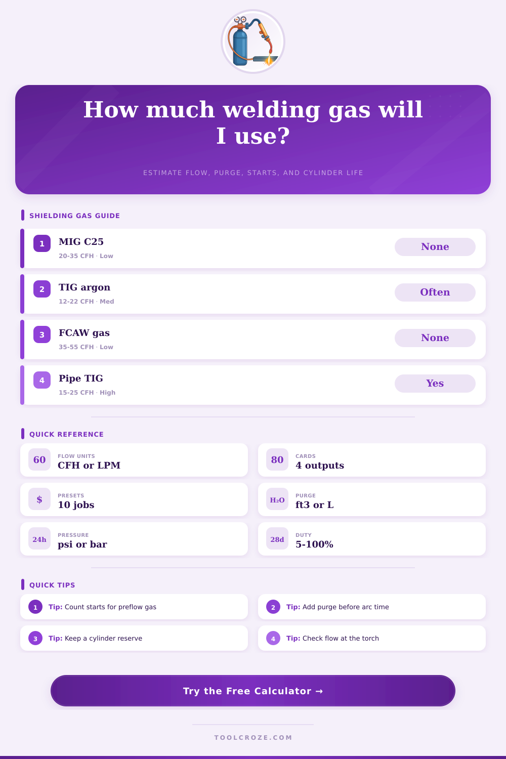
| MIG short circuit | 75/25 argon CO2 | 20 to 35 CFH / 9 to 17 LPM | Higher flow is not always better; excess flow can pull air into the nozzle stream. |
| MIG spray transfer | Argon rich with CO2 or O2 | 30 to 45 CFH / 14 to 21 LPM | Use clean cup coverage and confirm transfer mode before raising flow. |
| Gas-shielded FCAW | CO2 or argon CO2 blends | 35 to 55 CFH / 17 to 26 LPM | Field drafts and large nozzles often need more flow than bench MIG. |
| TIG mild or stainless | Argon | 12 to 22 CFH / 6 to 10 LPM | Postflow protects tungsten and hot weld metal after the arc stops. |
| TIG aluminum | Argon or argon helium | 15 to 28 CFH / 7 to 13 LPM | Large cups, helium blends, and AC cleaning can change the practical range. |
| Cylinder label | Nominal gas capacity | Typical full pressure | Planning use |
|---|---|---|---|
| Portable 40 | 40 ft³ / 1,133 L | 2,000 to 2,200 psi | Short repair work, small TIG jobs, and mobile carts. |
| Shop 80 | 80 ft³ / 2,265 L | 2,000 to 2,200 psi | Light fabrication and occasional bench welding. |
| Shop 125 | 125 ft³ / 3,540 L | 2,000 to 2,200 psi | Common small shop cylinder for MIG and TIG work. |
| Industrial 250 | 250 ft³ / 7,079 L | 2,000 to 2,400 psi | Longer weldments, purge setups, and production cells. |
| Industrial 330 | 330 ft³ / 9,344 L | 2,200 to 2,640 psi | High-use stations or shared manifolds. |
| Gas item | Formula used | Best input source | Watch point |
|---|---|---|---|
| Arc shielding gas | Flow rate x arc hours | Flowmeter while gas is flowing | Leaks and drafts can make readings misleading. |
| Preflow and postflow | Flow x starts x seconds | Machine timer plus segment count | Many short welds can use more gas than expected. |
| Purge fill | Volume x exchanges | Pipe ID, chamber volume, or fixture data | Complex geometry often needs extra exchange volume. |
| Purge hold | Purge flow x purge minutes | Dedicated purge regulator or meter | Keep purge low enough to avoid turbulence. |
| Cylinder remaining | Capacity x pressure ratio | Regulator pressure gauge | Keep reserve for shielding stability and changeover. |
Shielding gas are one of the consumable resources that the welder will use during the welding process. Shielding gas is consumed at a particular rate. Many welder are unaware that shielding gas is consumed not just while the arc is burning but also while the gases are preflowing and postflowing.
Preflowing is the shielding gas that flow before the arc is struck to the workpiece. Postflowing is the shielding gas that flows after the arc is extinguished after the welding process is completed. If an individual perform many short welds, a great amount of shielding gas will be consumed in the preflow and postflow gases.
How Shielding Gas Is Used and Wasted in Welding
This consumption will be more significant than the amount of shielding gas consumed while welding. To calculate the total consumption of shielding gas, there is several variables to consider. These include the total volume of the shielding gas, the flow rate at which the welder deliver the shielding gas to the weld area, and the number of times that the welder start the welding process.
The flow rate of shielding gas is often measured in cubic feet per hour. However, the measurement of shielding gas must be converted into minutes and seconds to understand the total amount of shielding gas available for welding. The higher the flow rate of shielding gas, the more rapid the welding process will consume the shielding gas.
For instance, a flow rate of 35 cubic feet per hour will deplete much faster than 20 cubic feet per hour. Purging of shielding gas is use in the welding of specific materials like stainless steel and titanium. During the purging process, the shielding gas is used to fill a particular volume of the material to be welded to remove oxygen from within the material.
The amount of shielding gas used during this process will depend on the size of the material being welded. The purging process consume a significant amount of shielding gas. In some instance, the entire cylinder of shielding gas will be used up prior to the welding process beginning.
The gas gauge on the shielding gas regulator may provide a welder with an indication of the amount of shielding gas remaining. However, this gauge isnt always accurate because the stability of the regulator can change as the shielding gas pressure drop. If the shielding gas pressure drops to a point where the flow rate may fluctuate, porosity may be introduced into the weld.
A reserve of at least ten percents of the total shielding gas should be maintained so that fluctuations in the flow rate are avoided. There are several way in which shielding gas will be wasted during welding. Shielding gas may leak from the welding hoses.
Shielding gas may be wasted during the setup of the welding equipment. Additionally, the shielding gas regulator may lose accuracy with time. If a welder use multiple torches connected to one manifold for the welding process, the amount of shielding gas that is wasted will increase.
Consequently, the amount of time that the shielding gas can be used during welding will decrease. Shielding gas flow rate should not be increased to provide more shielding for the weld. If the flow rate is too high, turbulence will be create in the shielding gas.
This movement of shielding gas may allow atmospheric gases to enter the weld. These gases will create porosity in the weld. The flow rate of shielding gas should be maintained at the level that is specifically recommend for the welding process being performed.
A planning of the shielding gas to be used during the welding process is a method of managing the risks of welding. The welder must determine whether the small tank of shielding gas is sufficient for the welding process or if a larger can of shielding gas are required. It is far more efficient for the welder to travel with one large cylinder of shielding gas than to travel to the welding vehicle for shielding gas on several occasions.
If the welder calculate the amount of shielding gas required to complete a particular job, then the welder can bid on the job accurate or schedule when to refill the shielding gas tanks for the welding process.