Welding Gas Calculator
Estimate shielding gas, purge gas, preflow, postflow, leak allowance, cylinder remaining volume, and run time for MIG, TIG, flux-core, plasma, and sanitary purge work.
Gas Calculation Breakdown
| Process | Typical gas | Flow range | Planning note |
|---|---|---|---|
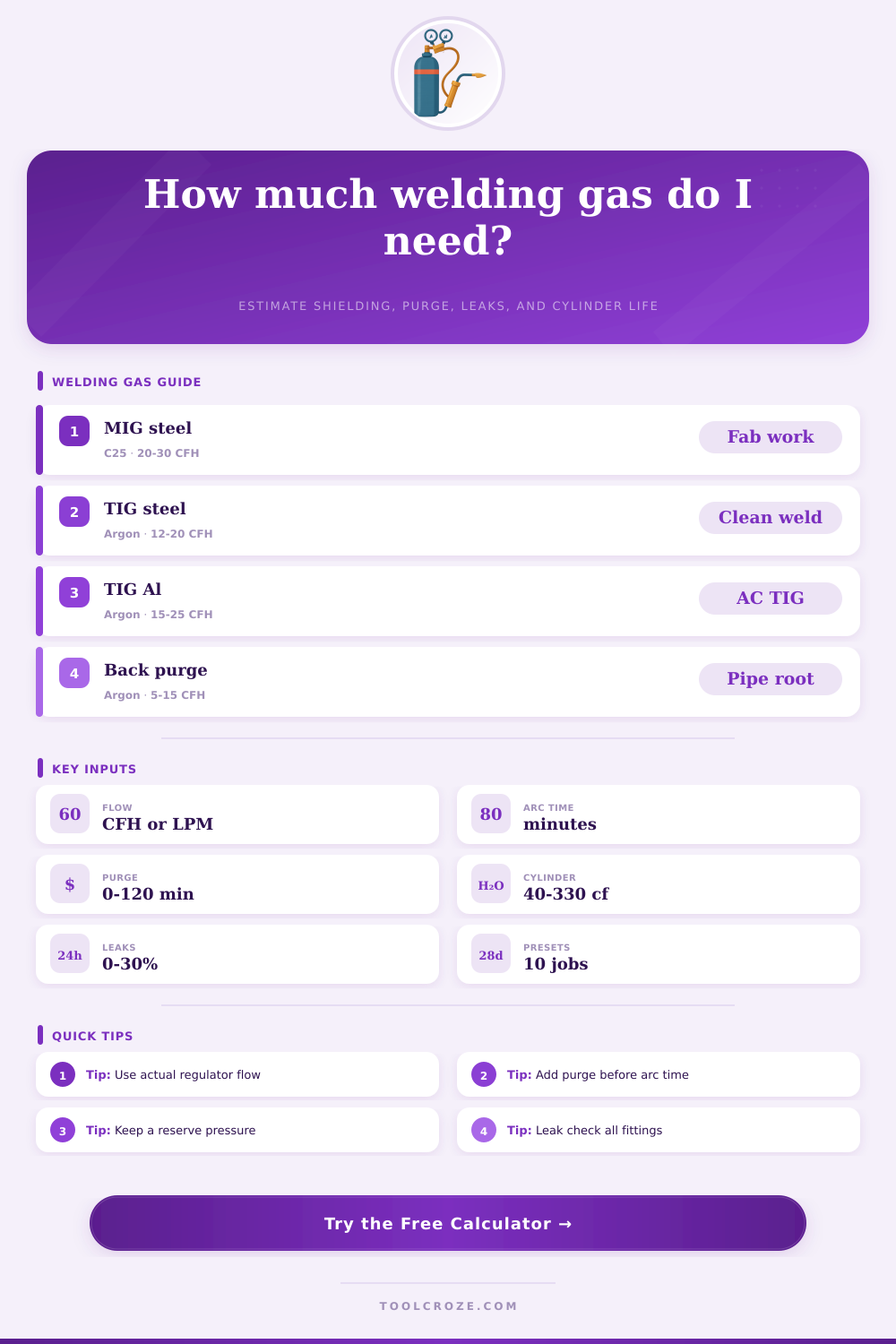
| MIG short-circuit steel | C25 argon / CO2 | 20 to 30 CFH | Raise flow for drafts, large nozzles, or long stickout. |
| MIG spray transfer | 90/10 or argon oxygen | 25 to 40 CFH | Spray arc often uses higher flow and cleaner gas coverage. |
| TIG steel or stainless | Pure argon | 12 to 20 CFH | Gas lens cups often use less flow than standard collet bodies. |
| TIG aluminum | Argon or argon helium | 15 to 25 CFH | Large cups, AC cleaning, and helium blends can need more flow. |
| Gas-shielded flux-core | CO2 or 75/25 | 30 to 45 CFH | Structural work outdoors needs wind control before more flow. |
| Cylinder | Rated gas | Common pressure | Approx 25 CFH time |
|---|---|---|---|
| Small portable | 40 ft³ | 2015 psi | About 1.6 hours when full |
| Medium shop | 80 ft³ | 2015 psi | About 3.2 hours when full |
| Large owner | 125 ft³ | 2015 psi | About 5.0 hours when full |
| Industrial high cap | 250 ft³ | 2265 psi | About 10.0 hours when full |
| Tall industrial | 330 ft³ | 2265 psi | About 13.2 hours when full |
| Purge job | Flow range | Exchanges | Planning note |
|---|---|---|---|
| Small stainless tube | 3 to 8 CFH | 5 to 8 | Use low flow to avoid turbulence and root oxidation. |
| Pipe spool root | 5 to 15 CFH | 6 to 10 | Count purge time before arc plus flow during the root pass. |
| Large vessel patch | 15 to 30 CFH | 6 to 12 | Chamber volume can exceed shielding gas use quickly. |
| Titanium enclosure | 10 to 25 CFH | 10 to 20 | Verify oxygen level before welding reactive alloys. |
| Food tube sanitary weld | 4 to 10 CFH | 6 to 10 | Use dams and oxygen monitoring for consistent color control. |
| Gas mix | Best fit | Typical effect | Calculator use |
|---|---|---|---|
| 100% argon | TIG, aluminum MIG, purge | Stable shielding and clean root protection | Use for most TIG and purge estimates. |
| 75/25 argon CO2 | MIG short arc steel | Softer arc with lower spatter than straight CO2 | Good default for light fabrication. |
| 90/10 argon CO2 | MIG spray steel | Supports higher deposition and spray transfer | Use with higher flow and longer arc times. |
| Argon helium | Aluminum, copper, thick TIG | More heat transfer and wider puddle | Track helium share for blend planning. |
| Argon hydrogen | Special stainless plasma or TIG | Hotter arc on compatible stainless work | Use only where procedure permits hydrogen. |
Shielding gas are a consumable that is used in the welding process. The welder must manage the shielding gas carefuly because shielding gas is used at a burn rate that is predictable. Although shielding gas may appear to be an unimportant component of the welding process, shielding gas is actualy essential to the process because shielding gas prevent the weld from becoming oxidized.
If the shield gas become depleted during a welding process, the weld will oxidize and will have to be ground out, requiring the welder to start the welding process over. While running out of shielding gas may be an inconvenience when working in a shop with no schedule for welding job, running out of shielding gas at a remote job site will kill the production schedule of that facility. In order to avoid running out of shielding gas, the welder must change from guessing the amount of shielding gas that remain in the cylinder to estimating how much shielding gas they will use during the welding process.
How to Estimate Shielding Gas for Welding
The flowmeter on the shielding gas cylinder will indicate the flow rate of shielding gas, but it will not show the total amount of shielding gas that is available for that days welding jobs. To calculate the amount of shielding gas that will be used during welding, several factor must be accounted for. Factors to consider include the amount of shielding gas that is used during preflow to clear the air prior to starting the weld, the amount of shielding gas that is used during postflow to protect the weld bead after the welding process, and any shielding gas that may be lost due to leaks in the systems fittings.
The flow rate of shielding gas is another factor that must be accounted for when calculating the amount of shielding gas that will be used during the welding process. The flow rate that is displayed on the regulator is the rate at which the shielding gas flows out of the cylinder, but the actual flow rate that hits the weld may be different. For example, if the shielding gas is pushed through a long lead or a narrow nozzle, less of the shielding gas will reach the weld than if the shielding gas was released from the cylinder without having to travel through a long lead or narrow nozzle.
Additionally, different welding processes will require different flow rates of shielding gas. For example, TIG welding will require a more higher flow rate of shielding gas than MIG welding. However, it is important to ensure that the flow rate is not too high, as high flow rates can cause the shielding gas to become turbulent, which may oxidize the weld.
Back purging of shielding gas is another process that requires a significant amount of shielding gas, and it is a process that many welder use that wastes shielding gas. In processes that involve high-pressure or sanitary processes, the interior of the pipe that is being welded requires its own atmosphere to prevent the weld from becoming oxidized. In order to purge the interior of the pipe of oxygen, the welder must use shielding gas to push the atmosphere out of the pipe.
The amount of shielding gas that is used for back purging is related to the volume of the pipe, so the welder must calculate the amount of shielding gas based off how many times the atmosphere in the pipe is to be exchanged with shielding gas. Another factor that must be considered is the start and stop cycles of the welding process. If the welder is welding long beads of metal, then the amount of shielding gas used during start and stop cycles will be minimal.
However, if the welder is welding many small tacks, the amount of shielding gas that is used during start and stop cycles will be much of the shielding gas that the welder consumes. The third factor that must be considered is the pressure of the shielding gas cylinder. The relationship between the pressure of the shielding gas cylinder and the amount of shielding gas that remains in the cylinder is linear.
To use this relationship to calculate the amount of shielding gas that will be used, the welder must know the capacity of the shielding gas tank. In addition, the welder must use the reserve pressure of the shielding gas cylinder so that when the shielding gas tank is nearly depleted, the regulator of the shielding gas will not act erratic. Erratic regulators can change the flow rate of the shielding gas that is delivered to the weld.
Finally, the amount of shielding gas that is lost due to leaks in the system must be accounted for. The shielding gas will naturaly escape through the solenoid valve, the connections in the hose, and the torch head. Therefore, it is always a good idea to estimate the amount of shielding gas needed by the welder plus some additional percentage of shielding gas to account for these possible leaks.
In other words, it is always better for the welder to have ten percent extra shielding gas than to be ten percent short of the amount of shielding gas required for the welding job. By tracking the amount of shielding gas that is used during arc time, purge volumes, and by monitoring the pressure in the shielding gas cylinder, a welder can create a logistics plan that will allow them to know the amount of shielding gas cylinders that they need to complete their welding job.