Welding Voltage Calculator
Estimate a practical arc voltage window from process, wire or electrode diameter, amperage, travel speed, material thickness, transfer mode, and gas mix.
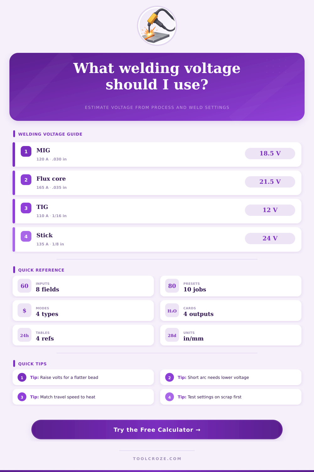
Choose a common shop weld. Each preset fills the fields and runs the voltage calculation.
Estimated welding voltage
Calculation breakdown
| Process | Typical mode | Amperage range | Voltage range |
|---|---|---|---|
| MIG solid wire | Short circuit | 70-180 A | 15.5-20.5 V |
| MIG solid wire | Spray transfer | 180-320 A | 23-30 V |
| Flux core wire | Gas or self shield | 110-280 A | 18-29 V |
| TIG DC or AC | Constant current | 30-250 A | 10-18 V |
| Stick electrode | Constant current | 45-220 A | 20-30 V |
| Wire or rod | Process fit | Typical amps | Voltage note |
|---|---|---|---|
| .023 in / 0.6 mm wire | Thin MIG sheet | 35-90 A | Low short-arc voltage |
| .030 in / 0.8 mm wire | General MIG | 55-150 A | Broad short-arc range |
| .035 in / 0.9 mm wire | MIG or flux core | 90-210 A | Needs more voltage above 160 A |
| .045 in / 1.2 mm wire | Spray or FCAW | 160-320 A | Usually 22 V and up |
| 3/32 in stick rod | Light SMAW | 45-90 A | Arc length controls voltage |
| 1/8 in stick rod | Common SMAW | 90-150 A | Mid 20 V arc common |
| Weld situation | Travel speed | Voltage effect | Check result |
|---|---|---|---|
| Thin sheet lap weld | 16-28 in/min | Lower voltage keeps puddle tight | Watch burn-through |
| 1/8 in fillet weld | 10-18 in/min | Moderate voltage wets toes | Check bead convexity |
| 1/4 in fillet weld | 7-14 in/min | Higher voltage flattens bead | Check fusion at root |
| Vertical-up weld | 4-8 in/min | Trim voltage down slightly | Keep puddle controlled |
| Spray plate weld | 10-20 in/min | Voltage must support spray arc | Confirm gas and amperage |
When you are welding, it is possible that the weld bead will have a convex shape with a rope like structure to it. This shape are typicaly caused by insufficient heat to melt the weld puddle into the metal of the workpiece. Many new welder will attempt to fix this problem by increasing the amperage.
However, amperage dont control the shape of the weld bead. Voltage do. If the weld amperage and voltage are not correctly balanced, the weld may have issues such as a bead that sit on the metal workpiece or a weld puddle that burn through the workpiece.
How Voltage Affects Weld Bead Shape
Voltage control the length of the welding arc. If you increase the voltage, the arc will stretch. The length of the arc will allow the weld puddle to wet the sides of the metal workpiece.
Higher voltage are required to produce a flat weld bead. Low voltages is useful in welding thin sheet metal but will not provide enough energy for a weld to be succesful when welding thick material such as heavy fillet weld. The variables in the welding process will alter the welding arc.
The variables is the diameter of the filler wire and the type of shielding gas used in the welding process. If the diameter of the filler wire are thicker, more energy will be required to melt it. Therefore, you must adjust the voltage to accommodate this change.
Argon-rich shielding gas require different settings than those using a pure CO2 gas. Argon-rich gas typically require higher voltage settings than CO2 gas to maintaining the same weld bead profile. Travel speed affect the amount of heat input into the metal.
If the travel speed of the welding metal is too slow, too much heat will be introduced into a small area of metal. This can cause the metal to warp. The travel speed should be matched to the voltage setting to control the heat input into the metal.
The metal being welded will dictate the proper setting that should be used on the weld machine. For thin metals, it take longer for the metal to soak up the heat from the welding arc. For this reason, thin metals require a lower voltage than thick metal.
Thick metals will act as a heat sink and draw the heat away from the weld. For this reason, an higher voltage is required to melt the thick metal sufficiently. Stickout is the distance between the contact tip of the welding rod and the metal workpiece.
This dimension affect the voltage of the welding process. In MIG welding, if you increase the stickout, the electrical resistance will increase. This will make the welding voltage higher even if the voltage dial isnt adjusted.
A longer stickout will allow for a more fluidly arc but may reduce the stability of the welding process. For TIG and stick welding, the welder can adjust the arc length with there hands. The welding machine provide a usable window of settings for voltage.
A higher voltage will create a wider and flatter weld bead. A lower voltage within this usable window will produce a weld bead that is tight to the workpiece. These voltage setting must be tested on a scrap piece of metal of the same material as the metal to be welded.
Welding are the interaction between three variables: amperage, voltage, and travel speed. Amperage melt the metal, voltage shape the weld puddle, and the travel speed determine the amount of heat that is placed into the metal. If the welder understands the function of each of these variables, they will have a better understanding of how to tune the weld machine to the welding metal.
By adjusting the voltage, the welder can balance the heat and the weld puddles flow to create a seamlessly joint.