Resin Print Angle Calculator
Estimate a practical SLA print angle from model height, base footprint, layer height, tilt, suction area, support density, hollowing, and resin drain planning.
⚙Print Presets
📐SLA Orientation Inputs
Resin Print Orientation Estimate
🧪Material And Print Behavior Grid
📊Angle Reference Table
| Print style | Starting angle | Why it helps | Watch for |
|---|---|---|---|
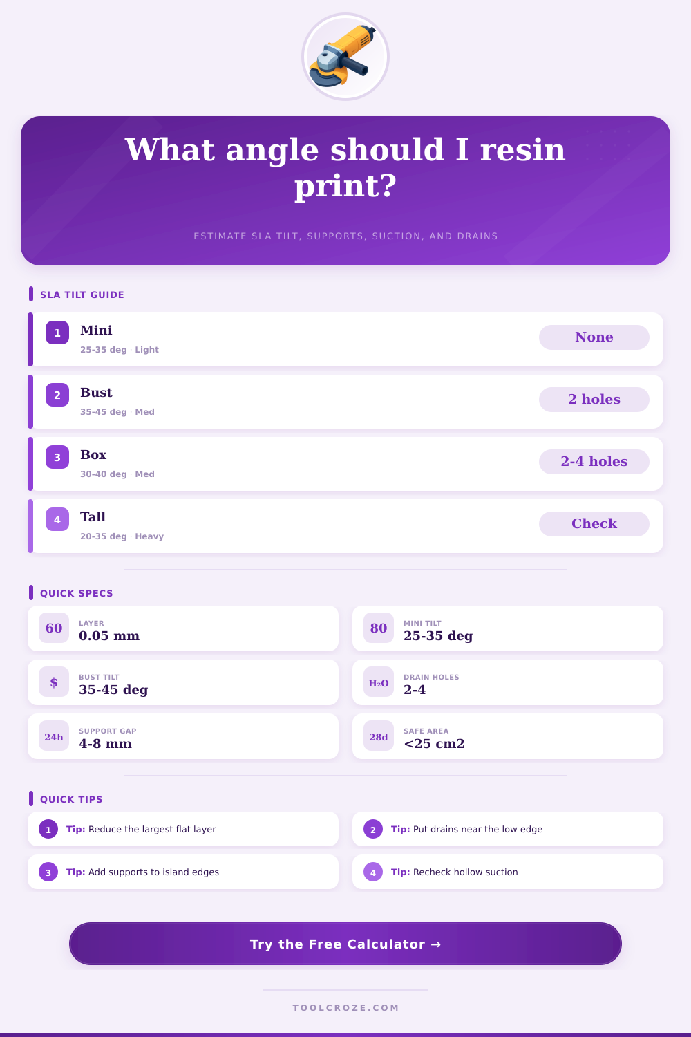
| Miniatures and figures | 25° to 35° | Reduces flat layers while preserving visible detail | Support islands under weapons, feet, and capes |
| Hollow busts and sculpts | 35° to 45° | Moves drain holes low and reduces suction cups | Large unsupported chin, hair, or shoulder islands |
| Flat plates and lids | 30° to 45° | Breaks up broad parallel layers | Warped edges from too few perimeter supports |
| Jewelry and dental detail | 20° to 35° | Keeps fine details from heavy support marks | Thin features bending during peel |
| Clear cosmetic parts | 40° to 55° | Moves marks away from optical faces | Long print time and visible layer stepping |
🔧Support Density Reference
| Density setting | Estimated spacing | Use when | Calculator effect |
|---|---|---|---|
| Light | 8 to 12 mm | Small display pieces with low peel load | Fewer supports, higher local load per tip |
| Medium | 6 to 8 mm | Balanced default for figures and prototypes | Normal support count and load sharing |
| Heavy | 4 to 6 mm | Large islands, heavy bases, and flat areas | More supports and lower failure risk |
| Dense | 3 to 5 mm | Tall, heavy, filled, or difficult resin prints | Maximum support count and surface cleanup |
💧Drain And Suction Reference
| Hollow condition | Drain plan | Typical diameter | Suction note |
|---|---|---|---|
| Solid miniature | No drain needed | 0 mm | Watch support load, not trapped resin |
| Small hollow figure | Two holes near low edge | 2 to 3 mm | One hole drains poorly and traps pressure |
| Medium bust | Two to three staggered holes | 3 to 5 mm | Add one vent opposite the main drain |
| Large prop shell | Four or more holes | 5 to 8 mm | Use multiple low points for wash access |
📋Preset Scenario Reference
| Scenario | Typical dimensions | Common angle | Planning note |
|---|---|---|---|
| Hero miniature | 52 x 36 x 28 mm | 28° to 35° | Keep supports off face and front detail |
| Display bust | 120 x 72 x 55 mm | 38° to 45° | Hollow, drain low, and add shoulder supports |
| Terrain tile | 80 x 80 x 10 mm | 35° to 45° | Direct flat printing can increase suction |
| Box lid | 110 x 70 x 4 mm | 35° to 50° | Support the rim evenly to limit warp |
| Large hollow shell | 180 x 130 x 90 mm | 40° to 55° | Drain holes and venting control success |
💡Resin Angle Tips
Suction is a common problem in SLA resin printing, and suction can cause the printed model to detach from the build plate. Suction can happen when the model act as a plunger. If the person prints a flat surface that is parallel to the resin vat, the flat surface will create a vacuum that can bend the supports and warp the printed model.
A way to prevent this type of suction failure is to change the orientation of the model. The orientation of the model affect the amount of suction that will act upon the printed model. When the model is tilted, the large flat surface that may have allowed for suction to occur is broken into smaller increments of surface area that will create less suction force upon the model.
Tilt the Model to Prevent Suction
Instead of the print head having to peel a large sheet of plastic off of the build plate film, the print head will be peeling many small slivers of plastic off of the film. A small change to the angle of the model can prevent a model from failing during the print job, and a small change in the angle of the model can save the resin cost for that model. The angle at which the model should be printed will depend upon the type of model that is to be printed.
For instance, if the model being printed is a miniature, the model will need to be tilted enough to prevent the supports from touching the face of the miniature when printed, but not tilted enough so that the layer line become visible upon the chest of the miniature. For models that are to be printed as hollow busts, the hollow bust model will need to be tilted to allow the resin to flow out of the hollow interior of the bust model. The print model will need to be tilted to such an angle to prevent the hollow interior of the model from creating a vacuum that will make it difficult for the supports to detach the model from the build plate.
The angle at which the model will be printed will also have an impact upon the total layer count of the model. As the angle of the model increase, the total layer count will increase. A tool is available on this page to calculate the risks of orientation of a model.
Such a calculator will ask for the dimension of the model to be printed and the angle at which the model will be printed. The software will calculate the area of the model that is in contact with the build plate. If the area of contact of the model with the build plate is too great, the forces of suction will be too great for the supports to handle.
The tool will allow the print designer to adjust the axis of the print model until the narrowest profile of the model is found. The less area of the model that is in contact with the build plate, the lower the risk that the print job will fail. The viscosity of the resin will also impact the suction force of the printed model.
Standard rigid resin will have a different viscosity than flexible resins or filled resins. High viscosity resin will have more of a tendency to cling to the FEP film than will low viscosity resin. Thus, high angle will be required when utilizing high viscosity resin compared to low viscosity resin.
Hollow print models will have the danger of the suction cup effect. If the hollow print model does not allow for air to enter the model or for resin to exit the hollow model, then the hollow print model will create a vacuum within the print model. Drain hole will need to be incorporated into hollow print models to prevent the creation of a vacuum within the printed model.
The drain holes will need to be placed on the lowest point of the hollow print model that is relative to the build plate. If the designer places the drain holes on the top of the hollow print model, resin will become trapped within the hollow model, and the weight of the trapped resin will create stress upon the supports of the model. The third factor to consider for successful resin printing is the support density that is used in the print job.
Too many supports will create a scarring of the printed model that will require sanding. Too few supports will create islands of plastic, which will be unsupported plastic that will cure within the air. The angle of the print model and the support density will have some relationship to one another.
As the angle of the model increases to reduce the suction forces that act upon the model, the total height of the model increases, which increases the amount of support structures required to support the tall model. The reference tables on this page will help print designer to determine the angle at which some common models should be printed to minimize the chances of failure. For instance, if the designer wants to print a flat terrain tile, that terrain tile can be printed flat.
However, by tilting the terrain tile to between 35 and 45 degrees, the designer can prevent the terrain tile from warping during the print job. The goal of the designer is to find a balance to the angle of the model that minimizes the suction forces acting upon the model while minimizing the support structures needed to support the model, and minimizing the visible layer lines of the printed model. Thus, resin printing is a process in which the designer must manage gravity, the surface tension of the resin between the model and the build plate, and the vacuum forces acting upon the model.
These forces can be managed through the use of the calculator provided on this page, and through the planning of the drain holes in the model prior to the start of the print job.