🔧 Pin Shear Stress Calculator
Check clevis pins, lug pins, dowels, brackets, hinges, and linkage pins for shear stress, bearing pressure, capacity, and edge margin.
📌 Pin Joint Presets
⚙ Calculator Inputs
📊 Results
🧪 Material / Spec Comparison Grid
📚 Reference Tables
| Joint type | Shear planes | Stress effect | Typical use |
|---|---|---|---|
| Single shear lap | 1 | Full load on one plane | Flat strap or simple bracket |
| Double shear clevis | 2 | About half the pin stress | Fork, yoke, and linkage joints |
| Three-plane yoke | 3 | Load spread over three cuts | Balanced specialty fixtures |
| Multiple pins | Pin count x planes | Shared only if stiffness matches | Fixtures, plates, and removable stops |
| Pin material | Shear strength | Yield basis | Best fit |
|---|---|---|---|
| Low carbon steel | 36 ksi / 248 MPa | Mild steel estimate | General shop pins |
| 4140 alloy steel | 60 ksi / 414 MPa | Heat treated pin stock | Machinery pivots |
| 304 stainless | 30 ksi / 207 MPa | Annealed stainless estimate | Corrosive service |
| 6061-T6 aluminum | 24 ksi / 165 MPa | Aluminum yield screen | Light brackets |
| Pin diameter | Area | Double shear area | 5 ksi capacity |
|---|---|---|---|
| 1/4 in | 0.0491 in² | 0.0982 in² | 491 lbf |
| 3/8 in | 0.1104 in² | 0.2209 in² | 1,104 lbf |
| 1/2 in | 0.1963 in² | 0.3927 in² | 1,963 lbf |
| 3/4 in | 0.4418 in² | 0.8836 in² | 4,418 lbf |
| Design check | Formula | Good screen | Watch item |
|---|---|---|---|
| Pin shear | P / (A x n) | Below allowable | Plane count |
| Bearing | P / (d x t x faces) | Below plate limit | Thin lugs |
| Edge distance | e / d | 1.5D or more | Tear-out risk |
| Clearance | Hole - pin | Small but free | Impact loading |
💡 Practical Tips
When you design a pin joint, you must account for shear stress. Shear stress is an internal force that try to slide one part of a solid material relative to another part of that same solid material. Pin failure dont usually occur due to a pin snapping in half.
Instead, pin failures occur due to the pin slicing through the cross section of the pin or the pin crushing the material that it are meant to support. You must choose a shear arrangement for the pin joint. One example of a simple lap joint is using a pin that pass through two plate.
How to Design a Strong Pin Joint
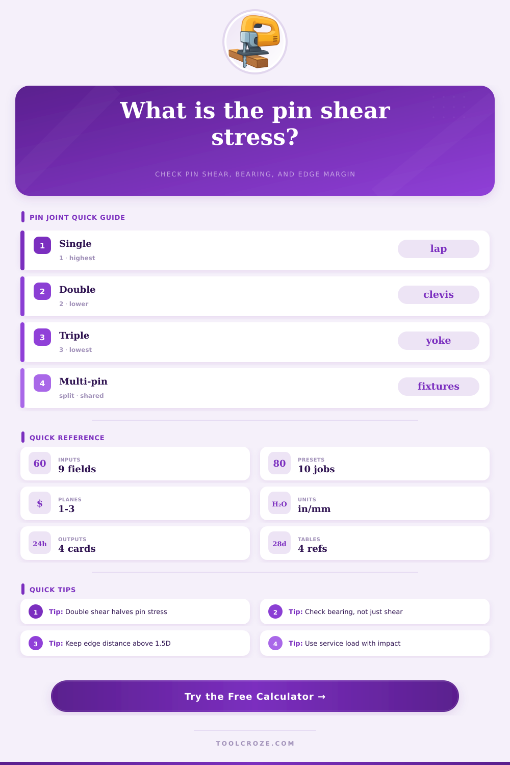
This arrangement creates a single shear plane. However, a clevis arrangement use a pin that passes through a fork and a center tongue arrangement. This arrangement creates double shear.
Using double shear, the load are distributed across two different shear planes, effectively doubling the strength of the pin without having to use a larger diameter pin for the pin. Another critical component in the design of a pin joint is the type of material for the pin. The strength of the pin must be compatible with the strength of the material the pin is joining.
For instance, using a Grade 8 steel pin is strong, but it may create deformation in a high strength steel pin because the steel pin is harder than the high-strength steel lug. When a pin pushes against the side of a hole, it create bearing pressure. Bearing pressure is the crushing force between the pin and the hole.
If the bearing pressure is too high, the hole will deform, and an oval-shaped hole can create slop and wobble in the joint. You can reduce bearing pressure by thickening the lug or the pin to provide a larger area for the pins to distribute the load over. Another consideration when designing a pin joint is the edge margin.
The edge margin is the distance from the center of the pin hole to the edge of the plate. If this distance is too small, the pin can tear a piece of the material out of the plate. This is known as a tearout failure.
To avoid this type of failure, the edge margin should be at least one and a half times the diameter of the pin. Many designer make the mistake of only calculating the shear strength of the pin, ignoring the bearing pressure on the hole or the edge margin of the plate. A pin joint is only as strong as it’s weakest component.
Therefore, the pin might be the strongest component in the joint, but if the plate is thin or the edge margin too small for the pin diameter, the joint will fail at the plate. Finally, another important element of pin joint design is the safety factor. Safety factors are used to account for dynamic loads or sudden shocks that the joint will experience in the real world.
If the pin joint will experience sudden movements, a higher safety factor is required. A safety factor of two might be sufficient for static loads in a controlled environment. However, a safety factor of three or four would be better for field applications of the pin joint.
When designing a pin joint, there are three distinct failure mode to manage: pin shearing, hole crushing, and edge tearing. You must manage these three failure modes to ensure that the pin joint is a reliable component of the machine it is use on.