🛞 Bolt Pattern Calculator
Convert lug count, bolt circle diameter, odd-lug measurements, and flange clearance into drill coordinates, hole spacing, and hub fit checks for wheels, adapters, and flanges.
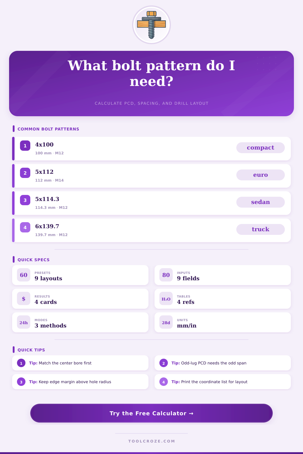
📌 Preset Layouts
⚙ Calculator Setup
🎯 Results
📊 Material and Spec Grid
36 ksi yield
54 ksi yield
40 ksi yield
73 ksi yield
31 ksi yield
Brittle section
Needs more stock
between bore and holes
📘 Reference Tables
| Passenger Pattern | PCD | Typical Stud | Common Fit |
|---|---|---|---|
| 4×100 | 100 mm | M12×1.5 | Compact Honda, Toyota |
| 5×10⁸ | 108 mm | M12×1.5 | Ford Europe, Volvo |
| 5×112 | 112 mm | M14×1.5 | VW, Audi, Mercedes |
| 5×114.3 | 114.3 mm | M12×1.5 | Accord, Camry, Altima |
| 5×120 | 120 mm | M14×1.25 | BMW, late GM |
| Truck Pattern | PCD | Typical Stud | Common Fit |
|---|---|---|---|
| 5×127 | 127 mm | 1/2-20 | Jeep Wrangler JK |
| 6×139.7 | 139.7 mm | M12×1.5 | Tacoma, Hilux, 4Runner |
| 8×170 | 170 mm | M14×1.5 | Ford Super Duty |
| 8×180 | 180 mm | M14×1.5 | Chevy/GMC HD |
| 8×165.1 | 6.5 in | 9/16-18 | Classic Dodge/GM HD |
| Stud Size | Close Hole | Service Hole | Notes |
|---|---|---|---|
| M12 | 12.5 mm | 14.0 mm | Typical passenger wheel clearance |
| M14 | 14.5 mm | 16.0 mm | Common on euro and HD hubs |
| 1/2 in | 0.515 in | 0.562 in | Jeep and older truck patterns |
| 9/16 in | 0.578 in | 0.625 in | Older 8-lug domestic hubs |
| Material | Edge Factor | Base Margin | Shop Rule |
|---|---|---|---|
| A36 / 1018 | 0.95-1.00 | 0.30 in | Good for steel spacers and flanges |
| 6061-T6 | 1.10 | 0.35 in | Add stock for repeated torque cycles |
| 304 stainless | 1.15 | 0.38 in | Work-hardens, avoid thin webs |
| Cast iron / poly | 1.25-1.35 | 0.45 in | Use wide flanges and slow drilling |
💡 Layout Tips
This calculator converts wheel and flange measurements into bolt circle diameter, hole spacing, and blank size checks so you can lay out lug patterns with cleaner drilling coordinates and safer edge margins.
A bolt circle is a pattern of evenly distributed hole on a circular component that allow a wheel to be secured to a vehicle hub. To fabricate a bolt circle, it is essential to determine the pitch circle diameter (also known as the PCD or pitch circle diameter). The PCD is a diameter of an imaginary circle that passes through the center of each lug hole on the component that feature the bolt pattern.
If you calculate the PCD incorrect, then the bolt circle will not be able to align to the components hub. Since the bolts will not be able to align with the holes on the components hub, the bolts will not be able to being secured to the component. Many bolt pattern include components that have an even number of bolt holes, such as 4 or 6 holes.
How to Measure and Make a Bolt Circle
These even numbers are easy to measure due to the even distribution of the bolt holes around the component. Five-lug component are more challenging to measure. The distance between two adjacent bolt hole can be measured.
Additionally, the distance from the edge of one bolt hole to the center of another bolt hole can be measured. These measurements can help determine the PCD of the component. Using these measurements, one can find the true PCD of the component.
Finding the true PCD is essential for ensuring that each hole is placed at the proper angle. When fabricating a bolt circle, it is necessary to consider the thickness of the material and the distance between the components hole. The thickness of the material must be sufficient to provide enough material between each bolt hole and the outer edge of the component.
This thickness of material is referred to as the edge margin. If there is not enough material in the edge margin, the component may crack under the torque that is applied to the bolt. Additionally, aluminum is a common material for bolt circles.
However, aluminum is a softer material than steel. Therefore, a component that is made from aluminum will need a larger edge margin than a component that is made from steel. Steel is a more stronger material than aluminum but is heavier than aluminum.
The material must also have enough thickness between the center bore and the lug holes. The center bore is the hole in the middle of the component that is used to allow the component to fit onto the hub of the vehicles wheel. If the metal web between the center bore and the lug holes is too thin, the component can vibrate or even break.
The diameter of the holes in the component must be slightly larger than the diameter of the bolts that will be used to secure the component. For example, if the bolts to be used on the component have an M12 size, then the diameter of the holes in the component should be approximately 14mm. Using a hole that is too small in diameter for the size of the bolts will prevent the bolts from being able to enter the component.
Using a hole that is too large in diameter for the size of the bolts will prevent the bolts from being able to sit secureley on the component. When drilling the component, you must determine the coordinates of the location of each hole. The X and Y coordinate can be used to determine the location of the center of each hole in the component.
Using the coordinates is the most accurate way to determine the location of the holes. Additionally, it will help to avoid any mistake when drilling the component. Using a CNC machine or a rotary table will allow the operator to enter the coordinates into the machine to drill the component in the necessary location.
The most essential factor to consider when fabricating any component is safety. A safety margin must be included to the measurement of any fabricated component. A safety margin of at least 10 or 20 percent is usually recommended.
The safety margin will ensure that there is enough material to withstand the torque created by the wheel. If there is no safety margin, the metal of the fabricated component may fail under the pressure of the mounted wheels. The measurement for the component must be verified against common bolt circle pattern.
These common pattern include 4×100, 5×114.3, and 6×100. If the calculations are found to be correct, then the bolts will tighten appropriately onto the component, and the wheel will remain secured to the vehicle. You should of checked the hole size before drilling. It’s important to be carefull because a mistake could mean the hole wont fit.
One of the most common mistake is thinking that the size of the bolt is the same as the hole. That isnt true. Also, making sure the hole is centered is vital, otherwise the hole might be off center and it will cause problems.
If you are using aluminum, its softer so you have to be extra carefull. One of the biggest issue is when the hole is too small and you cant get the bolt in.