🔧 Bolt Circle Calculator
Lay out flange, hub, wheel, and cover bolt patterns with exact spacing, XY coordinates, edge margin, and a drill-speed plan tied to real material data.
📌 Presets
⚙ Calculator Setup
🎯 Results
📍 Hole Coordinates
| Hole | Angle | X | Y |
|---|---|---|---|
| 1 | 90.0° | 0.000 | 2.250 |
📊 Reference Tables
| Pattern | Typical PCD | Angle Step | Common Use |
|---|---|---|---|
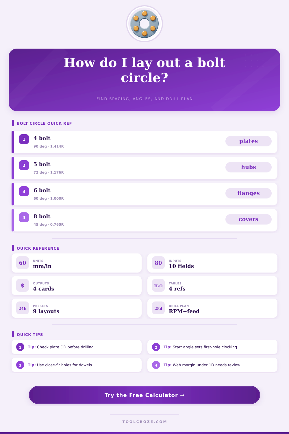
| 4 bolt | 3.00–5.50 in | 90° | Motor and servo flanges |
| 5 bolt | 4.50–5.00 in | 72° | Trailer and wheel hubs |
| 6 bolt | 110–139.7 mm | 60° | ATV, truck, and cover plates |
| 8 bolt | 6.50–8.75 in | 45° | Pump covers and heavy hubs |
| Bolt Size | Close Fit | Normal Clr. | Loose Clr. |
|---|---|---|---|
| 1/4 in | 0.266 in | 0.281 in | 0.312 in |
| 3/8 in | 0.406 in | 0.438 in | 0.469 in |
| M10 | 10.5 mm | 11.0 mm | 12.0 mm |
| M16 | 17.0 mm | 18.0 mm | 20.0 mm |
| Material | Min Web | Preferred Web | Shop Note |
|---|---|---|---|
| Mild steel | 0.50D | 1.00D | Stable with standard twist drills |
| 304 stainless | 0.75D | 1.25D | Favor rigid feed to avoid work hardening |
| 6061-T6 | 0.40D | 0.80D | Clear chips fast and deburr lightly |
| Acrylic | 1.00D | 1.50D | Use backing support to reduce breakout |
| Material | HSS SFM | Chip/Tooth | Typical Drill |
|---|---|---|---|
| Mild steel | 80 | 0.0025 in | 118° split point |
| 304 stainless | 45 | 0.0018 in | 135° cobalt |
| 6061-T6 | 220 | 0.0035 in | High-helix HSS |
| Cast iron | 70 | 0.0022 in | Standard HSS |
🗂️ Material and Spec Comparison
💡 Layout Notes
This bolt circle calculator gives spacing, coordinates, edge margin, and drill settings for hub and flange layouts. Use it to check fit, clocking, and drilling time before machining.
A bolt pattern is a set of hole that are arranged in a circle, and a bolt pattern is used to connect two part together. If the bolt pattern is misaligned, the parts wont be able to connect to one another, and the misalignment of the bolt pattern will cause the parts to wobble. The bolt pattern must be calculate in order to ensure that the parts will function proper.
A bolt pattern consist of a circle that is divided into an equal number of segment of the circle, indicated in degrees. A circle contains 360 degree. If there are four hole within the circle, one divides 360 by four to determine that the holes are spaced 90 degree apart from one another.
How to make a bolt pattern
If there are five hole within the circle, one divides 360 by five to determine that the hole are spaced 72 degrees apart from one another. Thus, in order to determine the angle of each hole within a pattern, one must divide 360 by the number of hole in the pattern. Such calculations must be precise to ensure that the worker correctly place each hole in the metal plate.
The chord length is the measurement between two adjacent hole within a bolt pattern, and the chord length is not the same than the arc length of the circle. The chord length is measured with calipers, which is a measuring tool that measure the distance between two point on the object. The chord length will be different if there is a different number of holes within the bolt pattern.
Thus, if the chord length is too short, the hole will be drilled too close to each other. If the chord length is too long, the bolt will not be able to preload the metal plate. Edge margin is the distance between the outermost hole within a bolt pattern to the outer edge of the metal plate.
The edge margin must be adequate in size to ensure that the metal will not crack along the edge of the plate. For metal plates made of steel, the edge margin should of be at least half of the diameters of the holes. For metal plates made of aluminum, the edge margin should be 40 percent of the diameter of the holes.
Otherwise, the metal plates may crack along the edge of the metal. The material of the metal plate will change the way in which the holes must be drilled within the bolt pattern. If the metal plate is mild steel, specific drilling speed must be used.
If the metal plate is made of stainless steel, the drilling speed are even slower because stainless steel is a harder metal to drill. Aluminum metal plates can be drilled at faster rate, but chips are produced that can become clog within the drill bit. A calculator must be used to determine the correct number of revolutions per minute (rpm) for the drill bit, as well as the drill bit’s correct feed rate.
Otherwise, the drill bit may become damage. Clocking is the process by which the orientation of the bolt pattern is set. Clocking will establish the starting angle of the bolt pattern.
For instance, if the start angle is set to zero degree, the first hole within the bolt pattern will be placed on the X-axis. If the start angle is set to 90 degrees, the first hole will be placed at the top of the circle. This starting angle does not impact the number of degrees of each hole within the bolt pattern.
Instead, the starting angle is used to set the bolt pattern to line up with the other metal components. The X and Y coordinate of the bolt pattern will determine where each hole is placed within the pattern. There are some common mistakes that one may commit in creating a bolt pattern.
For instance, one mistake is not checking the thickness of the metal plate between each hole. The metal may be too thin. Another mistake is using both inch and millimeters within the calculations for the bolt pattern.
This will lead to incorrect measurement. An incorrect start angle will prevent the other component made of metal to be interchangeable to those other metal parts. To complete the bolt pattern, the component should be center punched in the first hole.
Furthermore, one should verify the origin of the machine or the metal plate. After establishing the first hole at the appropriate size, the full circle should be scribe onto the metal plate. Finally, the holes should be deburred along the radial edge of each hole to ensure that the edge margin of the metal plate is preserved.
By following these steps, the bolt pattern will be accurate to the metal components.