🔩 Bolt Shear Stress Calculator
Estimate bolt shear stress, allowable stress, reserve margin, and minimum bolt count for lap joints, clevis joints, lugs, and structural splice plates.
📌 Joint Presets
⚙ Calculator Setup
🎯 Results
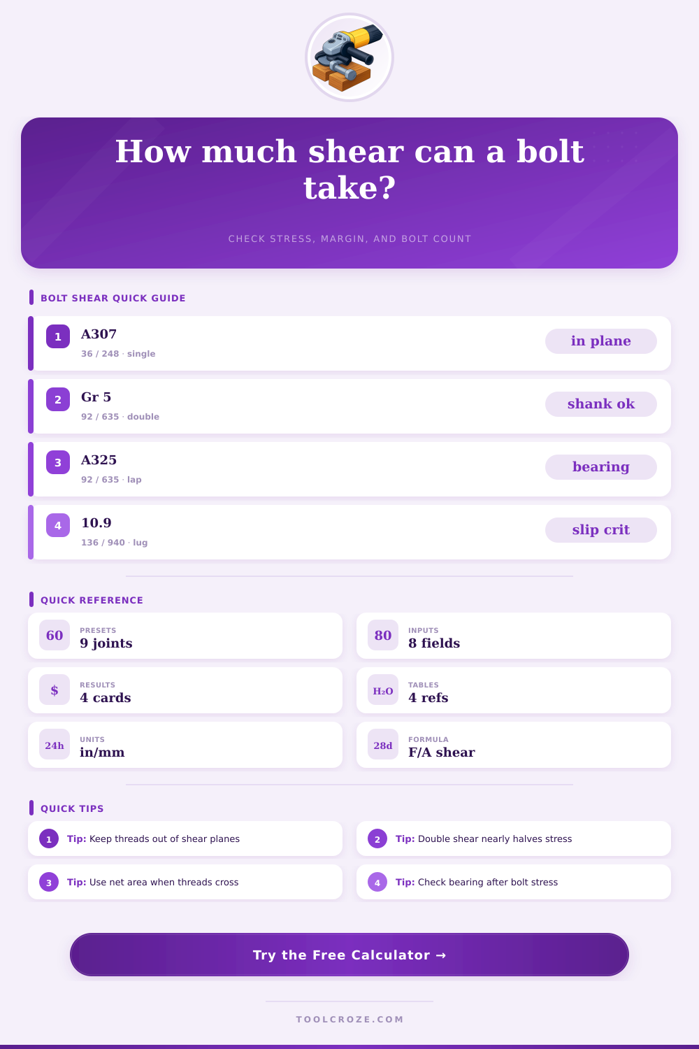
📊 Bolt Grade Comparison
General anchors
Machine joints
Steel splice work
High load lugs
📑 Reference Tables
| Grade / Spec | Fy ksi | Fy MPa | Typical use |
|---|---|---|---|
| ASTM A307 | 36 | 248 | Light anchors and supports |
| SAE Grade 2 | 57 | 393 | Guards, brackets, enclosures |
| SAE Grade 5 | 92 | 635 | Motor mounts and frames |
| SAE Grade 8 | 130 | 896 | Vehicle and heavy equipment |
| ASTM A325 | 92 | 635 | Structural steel connections |
| ASTM A490 | 130 | 896 | High-strength structural joints |
| ISO 8.8 | 93 | 640 | General metric machinery |
| ISO 10.9 | 136 | 940 | High-load metric machinery |
| A2-70 stainless | 65 | 450 | Outdoor corrosion exposure |
| Bolt size | Gross area in² | Stress area in² | Stress area mm² |
|---|---|---|---|
| 3/8 in | 0.110 | 0.0775 | 50.0 |
| 1/2 in | 0.196 | 0.1419 | 91.5 |
| 5/8 in | 0.307 | 0.2260 | 145.8 |
| 3/4 in | 0.442 | 0.3345 | 215.8 |
| M10 | 0.122 | 0.0899 | 58.0 |
| M12 | 0.175 | 0.1307 | 84.3 |
| M16 | 0.312 | 0.2434 | 157.0 |
| M20 | 0.487 | 0.3798 | 245.0 |
| Joint condition | Shear planes | Efficiency | Design note |
|---|---|---|---|
| Single lap | 1 | 0.80-0.90 | Eccentricity may raise bolt demand |
| Single lug | 1 | 0.85-0.90 | Check tear-out and bearing too |
| Double lug / clevis | 2 | 0.90-1.00 | Double shear reduces bolt stress |
| Double cover splice | 2 | 0.80-0.95 | Distribution depends on fit-up |
| Preset joint | Bolt | Load | Main reason |
|---|---|---|---|
| Base plate anchor | 1/2 in A307 | 6 kip | Low-strength anchor check |
| Guardrail splice | 5/8 in A325 | 18 kip | Common structural lap joint |
| Motor mount | M10 8.8 | 14 kN | Metric machine frame |
| Crane lug | M20 10.9 | 120 kN | High-load double shear joint |
💡 Design Tips
This calculator estimates bolt shear stress, allowable stress, utilization, and bolt count for common joints. Compare grades, shear planes, and thread position before final connection checks.
Shear stress are the force that acts on the bolt in teh direction that is parallel to the bolt shanks. Shear stress is different than tension stress in that tension stress acts to pull the bolt in a direction that is end to end of the bolt, but shear stress acts to slice the bolt sideways. If a bolt failure occur due to shear stress, the bolt may break.
If the bolt break, the joint will fail. Joint failure can result in a loss of time, a loss of money, or even a loss of safety. There are different type of shear configurations for bolts.
Shear Stress on Bolts and How to Check Strength
Each joint can be configured so that the load act in a single shear or in a double shear configuration. Single shear configuration can include lap joints. When the load acts on only one plane of the bolt, the threads of the bolt may be located within that shear plane.
If the threads of the bolt are within the shear plane, the effective area of the bolt is reduce. Because the area of the bolt is reduced, the strength of that bolt is also reduced. Double shear configurations can include clevis pin.
In these configurations, the load is distribute across two planes. By distributing the load across two planes, the strength of the bolt is reduced by approximately half. Bolt grade must be chose according to the load that will act on the bolt and the application of the bolt.
A307 (low-carbon) bolts has a yield strength of 36 ksi. A307 bolts are used for applications with modest load. Grade 5 (or A325) bolts have a yield strength of 92 ksi.
Grade 5 bolts are used for machine frame or structural splices. High-strength 10.9 metric and Grade 8 bolts has a yield strength of 130 ksi. 10.9 metric and Grade 8 bolts are used for heavy application, such as crane lugs or truck frames.
To calculate the allowable shear stress of a bolt, you should first multiply the yield strength of the bolt by.6. A safety factor divides this value. A safety factor of 1.5 is applied to factory environment.
A safety factor of 2.5 or 3.0 is applied to field environments due to the uncertainty of field conditions. In general, loads are distributed equally to each bolt within a group. However, within many joints, such as eccentric lap joints, the load is not share equally between the bolts within that group.
Therefore, each bolt within a group will not experience the same load. Additionally, the pitch of the bolt threads may factor into how strong the bolt will be. Coarse threads have more material than fine threads.
However, fine threads may reduce the effective diameter of the bolt if the threads are within the shear plane of the joint. To determine if a bolt is sufficient for a given load, a calculation process can be used. Such calculations require determine the type of joint, the specifications of the bolt, the number of shear planes, and the total load that is to act on the joint.
Input the shear force that is the worst-case scenario for that joint. Through the calculation, determine the stress on the bolt and the utilization ratio of the bolt. If the utilization ratio is > 100%, the bolt is undersized and another bolt larger than the current bolt should of been used.
Additionally, another group of bolts can be used. If the utilization ratio < 70%, the bolt has a margin of safety, but may be too large for the joint. In addition to shear strength, other failure mode of the bolt should be considered.
For example, bolts may pass the shear strength calculation, but may cause the metal plate to fail. In this case, the bolt can fail in a bearing mode. Bearing mode occur when the bolt crushes the hole in the metal plate.
Additionally, bolt holes should not be too close to the edge of the metal plate. Too close to the edge of a plate may lead to tear-out failure. Furthermore, bolts may be subjected to both tensile and shear loads at the same time.
This type of loading is refer to as combined loading. Safety factor are used to account for the strength of the material and the dynamic loads placed on that material. A safety factor of 1.5 is used to account for minor misfit in the joint.
A safety factor of 2.0 is used to protect against dynamic hits to the joint. If the joint is to be used in an environment with corrosion, such as outside in the rain or in contact with water, stainless steel may be use. Stainless steel has the advantage of being highly corrosion resistant.
The disadvantage of stainless steel is that it may have a lower strength than carbon steel. Overall, the designer is iterate until the utilization ratio of the bolt is within an acceptable range.