🔩 Bolt Strength Calculator
Estimate tensile proof capacity, shear strength, preload, and engagement reserve for common metric and unified bolt grades before you size a joint.
📌 Presets
⚙ Joint Inputs
🎯 Results
🗂 Material and Spec Comparison
📊 Reference Tables
| Bolt grade | Proof strength | Yield strength | Ultimate strength | Typical use |
|---|---|---|---|---|
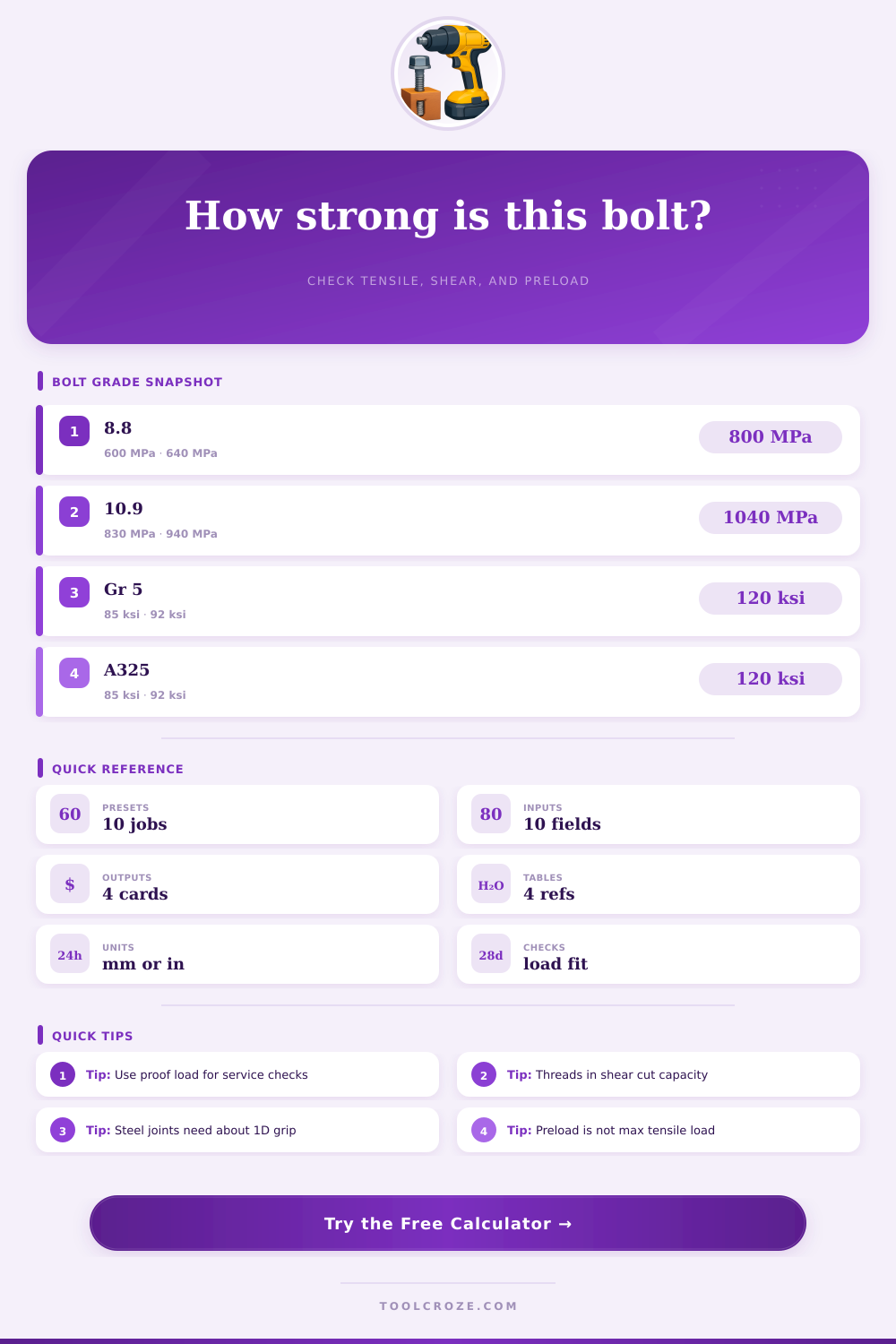
| ISO 8.8 | 600 MPa | 640 MPa | 800 MPa | General steel machine joints |
| ISO 10.9 | 830 MPa | 940 MPa | 1040 MPa | High clamp force assemblies |
| ISO 12.9 | 970 MPa | 1100 MPa | 1220 MPa | Socket head and compact high-strength joints |
| A2-70 stainless | 450 MPa | 450 MPa | 700 MPa | Indoor corrosion resistance |
| A4-80 stainless | 600 MPa | 600 MPa | 800 MPa | Marine or chloride exposure |
| SAE Grade 2 | 55 ksi | 57 ksi | 74 ksi | Light brackets and guards |
| SAE Grade 5 | 85 ksi | 92 ksi | 120 ksi | Automotive and fabricated frames |
| SAE Grade 8 / A490 | 120 ksi | 130 ksi | 150 ksi | Heavy equipment and structural tension joints |
| Metric size | Coarse pitch | Tensile area | Typical note |
|---|---|---|---|
| M6 | 1.0 mm | 20.1 mm2 | Small covers and clips |
| M8 | 1.25 mm | 36.6 mm2 | Light machinery brackets |
| M10 | 1.5 mm | 58.0 mm2 | Motor feet and guards |
| M12 | 1.75 mm | 84.3 mm2 | Medium structural clamps |
| M16 | 2.0 mm | 157 mm2 | Base plates and larger frames |
| M20 | 2.5 mm | 245 mm2 | Press frames and tie rods |
| Unified size | Coarse / fine | Tensile area | Typical note |
|---|---|---|---|
| 1/4 in | 20 / 28 | 0.0318 / 0.0364 in2 | Panels and electrical trays |
| 3/8 in | 16 / 24 | 0.0775 / 0.0878 in2 | Hitch and bracket work |
| 1/2 in | 13 / 20 | 0.1419 / 0.1599 in2 | Frames and suspension tabs |
| 5/8 in | 11 / 18 | 0.2260 / 0.2560 in2 | Structural splices |
| 3/4 in | 10 / 16 | 0.3340 / 0.3730 in2 | Crane and heavy bracket joints |
| Condition | Preload factor | Minimum engagement | Comment |
|---|---|---|---|
| Steel nut on steel bolt | 70-75% | 1.0D | Typical starting point for strong tapped joints |
| Cast iron or bronze thread | 60-70% | 1.5D | Use more thread length to reduce strip risk |
| Aluminum thread | 60-70% | 2.0D | Check thread strip separately for critical work |
| Slip-critical structural joint | 75-85% | Through-nut | Clamp force is often the governing target |
💡 Practical Notes
This calculator compares bolt grade, thread geometry, preload, and engagement so you can estimate usable tensile and shear capacity before checking the full joint design in detail.
Bolts is used to hold assemblies together, and the bolts must be selected based on there ability to resist specific force. There are two main types of force that affect bolts: tension and shear. Tension is the force that works to pull the bolt open, and shear is the force that works to slice the bolt sideways.
Because most assemblies will experience both types of force at the same time, bolts must be selected based on the ability of the bolt to resist both shear and tension forces. A calculator will help you to determine these forces because it permit you to choose between pure tension, single shear, and double shear forces. Shear forces have a different impact on the threads of the bolt than on the smooth part of the bolt; shear forces will reduce the bolt’s capacity to resist force if the bolt has threads rather than a smooth shank.
How to Choose the Right Bolt
The strength of a bolt can be determined by the grade markings stamp on the bolt. For metric bolts, the grade markings will be a number, such as 8.8 or 10.9, which will indicate the strength of the bolt. For instance, everyday machinery use metric bolts with an 8.8 grade, while 10.9 metric bolts are used for motor bases that must take higher clamp loads.
Imperial bolts will have markings of Grade 5 or Grade 8. Grade 5 bolts are used for automotive frames, while Grade 8 bolts are used for heavy industrial application like crane brackets. The strength of the bolt can also be described in terms of proof strength and yield strength.
Proof strength indicate the maximum load that a bolt can handle when subjected to repeated loads. Yield strength is the maximum load that the bolt can be subjected to before it undergoes permanent deformation. Proof strength is the better specification for bolt designer because the proof strength value of a bolt offers a margin of safety against overloading the bolt.
Bolts have a specified geometry that will impact the strength that the bolt will exhibit. The primary measurement of the bolt is its nominal diameter, such as M10 or 1/2 inch. The strength of the bolt is dependent upon the area of the thread root of the bolt.
UNC threads have a coarser measurement than UNF threads; the former is used to allow for faster installation of bolts and nuts, while the latter is used in case where there is a need for more grip between the mating components. The diameter of the thread root is determined by the pitch or threads per inch (TPI) of the bolt. A deeper thread will reduce the area at risk of being subjected to tensile loads.
If the area of the thread root is not taken into account when sizing bolts, a half inch bolt may not provide the same strength as a 7/16-inch bolt. The engagement length of a bolt is the portion of the bolt that are engaged in the mating component, such as a nut. The engagement length is important in determining the security of the bolt within the component.
For bolts that are secured into steel components, an engagement length equal to the bolt diameter is sufficient. However, for bolts that are secured into aluminum component, an engagement length that is twice the bolt diameter is required to avoid stripping the threads. Aluminum components have a lower strength than steel, so a longer engagement length is required to provide adequate strength for the bolt.
The engagement length must be establish before the assembly can be completed. Another specification for bolts is the preload. Preload is the tension that is applied to the bolt when it is installed into the component.
The preload set the clamp force of the component. For bolted assemblies, it is recommended to set the preload to 70 percent of the proof strength of the bolt. Using a preload that is too low will result in the component becoming loose.
Using a preload that is too high will result in the bolt fail due to factors like hydrogen embrittlement or cold seizure. When calculating the loads for bolted assemblies, it is important to consider how the load is distribute equally among the bolts. In an assembly that has four bolts and carries a 10,000-pound load, the load is not necessarily divided equally among the four bolts due to misalignment in the load path of the bolts.
To account for this possibility, a safety factor is incorporated into the calculations. A safety factor of 1.5 is used in structural frames that are static in their applications. For components that are subjected to dynamic loads, a safety factor of at least 2.0 is required.
The utilization of bolts in a bolted assembly can be measured. The ratio of the load on the bolt to its proof strength provides a value that indicates the degree of load of the bolt relative to its strength. A rate that is below 85 percent of the proof strength is considered safe for most application.
Materials can also impact the performance of bolts in a bolted assembly. For instance, if bolts of a higher strength than the aluminum component are used, the bolts may experience galling when they are being tightened. The materials that are used for bolts and components must be compatible with each other.
The engagement length of the bolt must be adjusted to account for the material of the component that is to be joined. If the threads of the bolt are in the shear plane of the joint, the capacity of the bolt will be reduced to 70 percent of its strength. This is because the bolt will fail under shear loads.
Fatigue is the phenomenon wherein the bolt weaken due to the application and removal of tensile forces. Dynamic loads cause fatigue damage to the bolt, so a higher safety factor is required for bolts that are used in dynamic applications.