🔨 Scallop Height Surface Finish Calculator
Predict cusp height, estimate Ra, and tune stepover for smoother CNC finishing across flat, blended, and 3D surfaces.
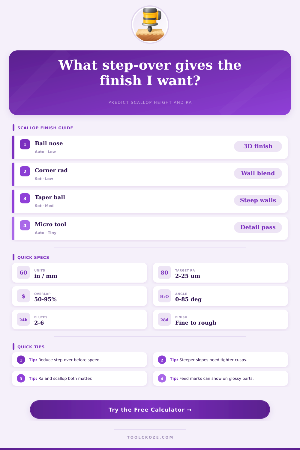
📌Preset Finishes
📊Calculator Inputs
✅ Finish Results
🧰Finish Factor Grid
📋Material Finish Reference
| Material | Finish factor | Typical Ra | Note |
|---|
📊Tool Profile Reference
| Profile | Radius rule | Step-over rule | Use |
|---|
📐Scallop Matrix
| Step-over | Scallop | Ra estimate | Finish class |
|---|
📋Finish Strategy
| Goal | Scallop limit | Overlap | Action |
|---|
Scallop height is an measurement of the ridges that are left behind on a workpiece by a cutting tool. These ridges is caused by the tool paths that the cutting tool take; as the cutting tool pass over the workpiece, the tool leaves behind a ridge that contains small cusps on the workpiece. The scallop height for a workpiece is the result of the tool’s stepover and radius.
The stepover distance and the tool’s radius are the two variables that determine the height of the scallops that will appears on the workpiece. If the stepover is large, the scallop height will be large. Conversely, if the stepover is small, the scallop height will be small.
What is scallop height and how to control it
The angle of the workpiece’s surface impact the scallop height. Tools like ball-nose endmills cut in an arc. The radius of the endmills’ nose and the distance between each pass determine the height of the scallop that is formed between each pass.
However, the angle of the workpiece impact the effective stepover. If the workpiece’s surfaces is tilted in relation to the cutting tool, then the scallop heights will appear higher than they would if the workpiece had been flat. In this situation, a calculator that accounts for the angle of the workpiece’s surface will calculate the scallop height that will result on the workpiece.
The material that is being cut will also impact the appearance of scallop heights on the workpiece. Aluminum can accept a bright polish, meaning the scallops will go unnoticed on aluminum workpieces. However, stainless steel and cast iron are much harder material.
Therefore, the scallop heights will be more visible on workpieces made of these materials. Wood workpieces can also be impacted by scallop heights. If the workpieces are made of wood, then large scallop heights may be visible as glue lines on the workpiece.
A stepover must be chosen that is appropriate for the material being machine. Stepover is not the only factor that impact the roughness of a workpiece. Feed marks will also contribute to the roughness of the workpiece.
The cutting tool’s feed rate and the chip load on the workpiece cause feed marks. Feed marks contribute to the Ra value of the workpiece. The Ra value is a measurement of the average roughness of the workpiece’s machined surface.
Feed marks can be minimized by reducing the feed rate and using a high RPM. However, scallop height will remain the primary factor that impact roughness on steep slope on a workpiece. Stepover should be reduced before cutting speed is increased to compensate for scallop height.
A range of cutting tools can be used in a milling operation to control scallop height. If a job require a tool that can perform fillet blending operations, corner radius tools can be used. These tools will create a better blend into the fillet than a ball-nose tool.
Tapered ball-nose tools are also available and can maintain tool contact with steep walls. If time is of the essence in a project, presets for materials like steel and acrylic can be utilized. These tools will recognize the material being machined and change to provide appropriate diameter and angles for the material.
A safety trim can also be used to reduce the stepover by ten percent. The total number of passes that a cutting tool will take on a workpiece must be considered when calculating the stepover. A small stepover will result in a low scallop height.
However, it will also require a high number of passes to complete the workpiece. More passes will take more time to machine the workpiece. The pass count will provide insight as to whether low scallop height with a high number of passes or a larger scallop height with fewer passes is preferred.
It is also important to understand the difference between scallop height and Ra. Ra is the average roughness of the workpiece. Scallop height is the depth of the ridge between passes of the cutting tool.
A workpiece can have a low Ra but high scallop heights that is visible to the naked eye. The percentage of overlap that the tool takes on the workpiece can be adjusted to create different finish on the workpiece. If the customer desires a satin finish, set the tool to an overlap of 65 to 82 percent.
If the customer desires a mirror finish on the workpiece, set the overlap to 88 percent or more. However, if the workpiece is made of aluminum, use ball-nose cutters. If performing rest machining, the stepover can be larger since this operation removes the material that has previously camouflaged scallop heights.
Finally, the use of finish class labels can tell the operator what type of finish will be create on the workpiece. The “fine” label indicates a low scallop height while the “rough” label indicates a larger scallop height. Both labels will help the operator understand the workpiece after it has been machined.
Finally, the results of a workpiece can be verified with a test coupon. A test coupon will allow the operator to machine a sample workpiece to test the scallop height and the feed marks on a workpiece. By using a test coupon, the operator will be able to ensure that the workpiece will meet the requirements of the customer.
However, it is also essential to be aware of the physical limits of the workpiece. These limits include tool stickout, spindle wander, and workholding chatter. These three factor will impact the quality of the workpiece regardless of the calculations of the scallop height.
By adjusting the stepover of the cutting tool, the operator can control the scallop height on the workpiece.