Hole and Shaft Tolerance Calculator
Compare hole limits, shaft limits, fit behavior, and measured parts with one precision calculator.
Calculation breakdown
| Nominal diameter | -- |
| Diameter band / D | -- |
| Tolerance unit i | -- |
| Hole tolerance width | -- |
| Shaft tolerance width | -- |
| Hole limits | -- |
| Shaft limits | -- |
| Theoretical clearance range | -- |
| Finish stock estimate | -- |
| Actual fit status | -- |
| Diameter band | Geometric mean D | IT7 width | Notes |
|---|---|---|---|
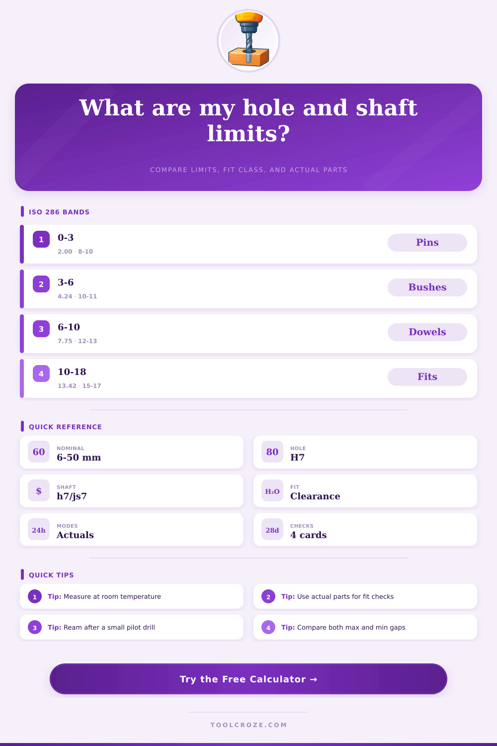
| 0 to 3 mm | 2.000 mm | about 10 µm | Small pins and locating dowels |
| >3 to 6 mm | 4.243 mm | about 11 µm | Tight small bush and hinge fits |
| >6 to 10 mm | 7.746 mm | about 13 µm | Common precision drill and pin work |
| >10 to 18 mm | 13.416 mm | about 16 µm | Shop reamers and tooling shafts |
| >18 to 30 mm | 23.237 mm | about 19 µm | Fixture bores and medium shafts |
| >30 to 50 mm | 38.730 mm | about 22 µm | Hardware, hubs, and guide pins |
| >50 to 80 mm | 63.246 mm | about 25 µm | Large collars and machine parts |
| >80 to 120 mm | 97.980 mm | about 29 µm | Heavy-duty fit and alignment work |
| Pair | Clearance window | Typical use | Fit type |
|---|---|---|---|
| H7 / h7 | 0 to IT sum | Locating dowels | Clearance |
| H7 / js6 | Centered | Snug assembly | Transition |
| H7 / js7 | Near zero | Careful slip fit | Transition |
| H7 / h6 | Slightly open | Precision pins | Clearance |
| H8 / h7 | More open | Free-running fit | Clearance |
| H7 / h8 | More open | Easy assembly | Clearance |
| Sample size | Hole min-max | Shaft min-max | Practical note |
|---|---|---|---|
| 6 mm | 6.000-6.011 | 5.989-6.000 | Popular dowel size |
| 8 mm | 8.000-8.014 | 7.986-8.000 | Tooling and guides |
| 10 mm | 10.000-10.016 | 9.984-10.000 | Fixtures and bushings |
| 12 mm | 12.000-12.016 | 11.984-12.000 | Workshop alignment |
| 16 mm | 16.000-16.018 | 15.982-16.000 | Heavier parts |
| 25 mm | 25.000-25.020 | 24.980-25.000 | Large bore fit |
| Process | Target before finish | Watch for | Best result |
|---|---|---|---|
| Drill | 0.10-0.30 under | Runout | Ream after drilling |
| Ream | Near nominal | Chip load | Clean bore |
| Turn | 0.02-0.08 over | Tool wear | Ground or skim finish |
| Grind | Very near nominal | Heat | Stable shaft size |
| Gauge | Check limits | Temperature | Room-temperature reading |
| Press | Measure first | Surface damage | Repeatable assembly |
Hole shaft tolerance is all about how a shaft fits into a hole. In engineering each shaft and hole has a tolerance range, that allows a bit of variation in size to ensure proper function. During precise production a shaft 0.01 mm too thick can jam in the hole and a hole 0.005 mm too narrow can entirely stop the assembly.
Three basic kinds of fits exist: clearance fit, interference fit and transition fit. In clearance fit between shaft and hole always stays a gap, even when the shaft is thickest and the hole narrowest, it then slips freely through. Interference fit is also called press fit, tight fit or friction fit; you use them for setting a bearing to shaft or hole, or for pressing a dowel pin in a hole.
How Hole and Shaft Sizes Fit Together
Transition fit requires precise alignment of the parts, that fit together without too much play or motion in the assembly.
ISO system of limits and fits include hole and shaft tolerances of a bit above 0 until 500 mm. You count them according to standard classes and limit deviations from ISO 286-2:2010. Letters in the tolerance code show the fit: R for sliding or running, L for location or alignment, F for force or shrink.
Numbers mark the grade, from 1 very loose until 9 very tight.
For instance H7 hole has always positive allowance, so 10 mm hole measures between 10.000 and 10.018 mm. P6 shaft ensures interefrence in 10.022 until 10.035 mm. 30h7 shaft has tolerance zone of 0 up and -0.021 mm below, so that it ranges between 29.979 mm and 30.000 mm.
It does not matter whether hole has positive tolerance, shaft can be bigger than it, if the tolerance zone is quite broad. It is a good way to use always H7 for holes. Makers like this use same reamers and gauges.
You call that hole basis fits, rather than shaft basis fits, that are less commonly used. Different sizes are much more easily made and measured.
Expert makers usually offer proper tolerances for shaft and housing. Generally you want the broadest possible, for ease of machining while you get the wanted fit. If a bearing slips on with little tap of a hammer, it works for one part, but for several parts precise tolerances becomeessential.