ISO Tolerance Calculator
Calculate ISO hole limits, shaft limits, and fit windows with one precision calculator.
Calculation breakdown
| Nominal diameter | -- |
| Diameter band / D | -- |
| Tolerance unit i | -- |
| Hole tolerance width | -- |
| Shaft tolerance width | -- |
| Hole limits | -- |
| Shaft limits | -- |
| Theoretical clearance range | -- |
| Finish stock estimate | -- |
| Actual fit status | -- |
| Diameter band | Geometric mean D | IT7 width | Notes |
|---|---|---|---|
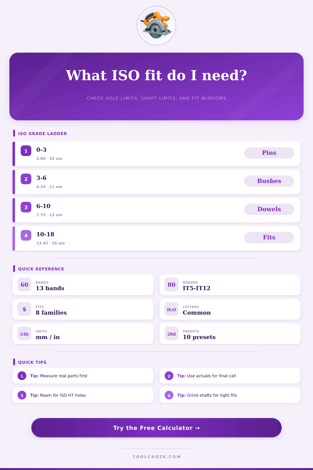
| 0 to 3 mm | 2.000 mm | about 10 µm | Small pins and locating dowels |
| >3 to 6 mm | 4.243 mm | about 11 µm | Tight small bush and hinge fits |
| >6 to 10 mm | 7.746 mm | about 13 µm | Common precision drill and pin work |
| >10 to 18 mm | 13.416 mm | about 16 µm | Shop reamers and tooling shafts |
| >18 to 30 mm | 23.237 mm | about 19 µm | Fixture bores and medium shafts |
| >30 to 50 mm | 38.730 mm | about 22 µm | Hardware, hubs, and guide pins |
| >50 to 80 mm | 63.246 mm | about 25 µm | Large collars and machine parts |
| >80 to 120 mm | 97.980 mm | about 29 µm | Heavy-duty fit and alignment work |
| Pair | Clearance window | Typical use | Fit type |
|---|---|---|---|
| H7 / h7 | 0 to IT sum | Locating dowels | Clearance |
| H7 / js6 | Centered | Snug assembly | Transition |
| H7 / js7 | Near zero | Careful slip fit | Transition |
| H7 / h6 | Slightly open | Precision pins | Clearance |
| H8 / h7 | More open | Free-running fit | Clearance |
| H7 / h8 | More open | Easy assembly | Clearance |
| Sample size | Hole min-max | Shaft min-max | Practical note |
|---|---|---|---|
| 6 mm | 6.000-6.011 | 5.989-6.000 | Popular dowel size |
| 8 mm | 8.000-8.014 | 7.986-8.000 | Tooling and guides |
| 10 mm | 10.000-10.016 | 9.984-10.000 | Fixtures and bushings |
| 12 mm | 12.000-12.016 | 11.984-12.000 | Workshop alignment |
| 16 mm | 16.000-16.018 | 15.982-16.000 | Heavier parts |
| 25 mm | 25.000-25.020 | 24.980-25.000 | Large bore fit |
| Process | Target before finish | Watch for | Best result |
|---|---|---|---|
| Drill | 0.10-0.30 under | Runout | Ream after drilling |
| Ream | Near nominal | Chip load | Clean bore |
| Turn | 0.02-0.08 over | Tool wear | Ground or skim finish |
| Grind | Very near nominal | Heat | Stable shaft size |
| Gauge | Check limits | Temperature | Room-temperature reading |
| Press | Measure first | Surface damage | Repeatable assembly |
The ISO tolerance is standard system that you use in machining and production to control whether parts fit. It ensures fit without friction vibration or wear. The system bases on ISO 286 that relates especially to tolerances for cylindrical surfaces and distances between parallel planes as in shaft and hole systems
Big letters, for instance H7, point to internal sizes, so holes. Little letters, as h7, show outside sizes, so shafts. The number points the scope, so that H7 have more tight tolerance zone than H11. Basicly the letter shows the type of fit, whether loose or press, while the number give the manufacturing accuracy of that fit.
ISO Tolerance for Holes and Shafts
Hole with size 4 H7 range between 4,00 and 4,012 mm. Shaft in 4 h7 go from 3,988 until 4,00 mm. ISO 286 lists favored tolerance classes for holes, among that are G7, H7, JS7, K7, N7, P7, R7, S7, F8, H8, E9, H9, D10, A11, B11, C11 and H11. The tolerances change according to the size.
IT grade classifies group of tolerances. Each from them marks by IT with precise grade, as IT01, IT0, IT1 until IT18. The size of the tolerance zone matches to the allowed variation of the size.
You measure tolerance widths in microns for particular nominal size ranges and IT grades.
ISO 2768 give general standard tolerances in millimeters for linear and angular sizes, where are no individual signs. It deals with linear sizes, exterior edges and chamfer heights, straightness and flatness, perpendicularity, symmetry and runout. Usually you write in the title block, that all tolerances are ± certain amount, unless otherwise noted.
For particular size with other tolerance you write it directly at that size.
Inspection teams apply the ISO standard and tolerance tables for go/no-go gauging and statistical process control. It gives clear pass/fail criteria. ISO 286 also ensures tools and gauges answer for make holes and shafts according to the standard tolerances.
Standardizing on tolerancing fits for bearings, dowel pins and other tight tolerance bits, so that everything stay uniform and any engineer does not interpret on there own. Are websites with calculators, that allow you to enter nominal diameter, choose tolerance grade and receive the upper and lower limit. Those tools operate for nominal diameters of 0 until 500 mm.
Around 0,125 mm is exactly the limit between easy and fast setup without special preparations. More tight than that causes costs grow. Modern CNC machines however can easily reach more precise tolerances.