Steel Road Plate Load Capacity Calculator
Estimate road plate wheel capacity, bending stress, deflection, bearing pressure, and minimum thickness for a temporary trench cover.
Calculation Breakdown
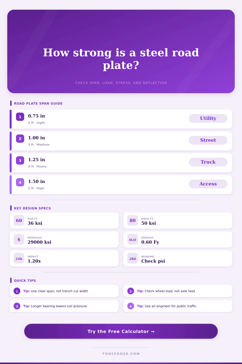
| Plate thickness | Common clear span | Typical traffic screen | Practical note |
|---|---|---|---|
| 0.75 in plate | Up to about 2 ft | Light vehicles, short exposure | Often controlled by deflection and bearing |
| 1.00 in plate | About 2 to 3 ft | Passenger cars and light trucks | Check truck wheel load before using in traffic |
| 1.25 in plate | About 3 to 4 ft | Urban truck traffic screening | Stiffer approach ramps reduce impact demand |
| 1.50 in plate | About 4 to 5 ft | Heavy work zone access | Confirm lifting weight and edge seating |
| Steel specification | Yield strength used | Elastic modulus | Best fit for road plates |
|---|---|---|---|
| ASTM A36 | 36 ksi | 29,000 ksi | Common mild steel trench plates |
| ASTM A572 Grade 50 | 50 ksi | 29,000 ksi | Higher bending capacity at same thickness |
| ASTM A588 | 50 ksi | 29,000 ksi | Weathering plate where corrosion exposure matters |
| ASTM A514 | 100 ksi | 29,000 ksi | High-strength plate needing weld and notch review |
| Traffic condition | Suggested impact factor | Wheel load input | Check emphasis |
|---|---|---|---|
| Static equipment parking | 1.00x | Actual tire reaction | Bending stress and bearing pressure |
| Slow work zone crossing | 1.10x | Heaviest single wheel | Deflection and plate seating |
| Normal street traffic | 1.20x | Truck wheel load | Impact, stress, and approach smoothness |
| Bus, fire, or rough approach | 1.30x to 1.50x | Published axle reaction split to wheels | Engineer review and anchorage |
| Calculated signal | Green range | Review range | Action if high |
|---|---|---|---|
| Bending utilization | Under 75% | 75% to 100% | Increase thickness, reduce span, or change grade |
| Deflection ratio | L/360 or stiffer | L/240 to L/360 | Add support, shorten span, or thicken plate |
| Bearing pressure | Below surface limit | Near surface limit | Increase bearing length or improve bedding |
| Plate weight | Within lift plan | Near lift limit | Confirm rigging, lifting points, and handling |
A delivery truck is idling; you’re standing on the lip of a deep trench. The driver glances at his watch, and you glance down at a steel plate lying on the ground. It’s heavy, it’s strong… but will it bend under weight of eighteen tons?
This is where engineering reality meets the point where a steel road plate becomes a structural puzzle. The puzzle involve bearing pressure on soil beneath, bending stress, and deflection limits. Everyone thinks it’s all about thickness, “I need a thick plate to solve everything.” Well yes it will help but then span length comes into play. Every time you double your support point separation, you quadruple your load. If a 1″ plate covers two feet, you’re good… cover four feet with it and you’re done.
How to Choose a Steel Road Plate
I’ve run those numbers in the calculator above so it does the work for you; you just input correct values. Measure the span correctly: this is the most common trap. The clear span is not hole size or the saw cut size; it is the unsupported distance from one solid edge to another. Designing based off bearing edges will result in a plate less strong than needed. Worse yet, designing without accounting for a soft spot and thus underestimating the span can mean designing a plate that won’t hold up. Clear span = what it says.
Okay, then there’s the load. Don’t go by axle weight; we’re after wheel weight here. Even though an axle in a semi-truck can holds twenty thousand pounds, that load is distributed between dual wheels. What the calculator wants is single wheel load since that’s the maximum bending moment (concentrated force). Reducing the load to two or more tires decreases the stress per square foot of plate where any tire touches down. If you inform the calculator about spacing of your tires, it will handle the load distribution for you and determine whether it’s concentrated or spread out.
The type of steel also make a difference and it isn’t as simple as saying “buy thicker steel.” The cheapest and most commonly available steel is standard A36 mild steel that will yield at thirty-six thousand pounds per square inch. However, if you buy A572 Grade 50 steel, it has a yield of fifty thousand. So you can get away with thinner plate to carry the same load and span with greater strength, but then steel costs something. Lifting a two-thousand pound plate is going to be rigged different than a five-thousand-pound one. A heavier plate means using thicker ones, and those are just heavier. You really can’t disregard weight because there’s always a tradeoff between how much the thing weighs and how much it costs in material.
The silent killer is deflection. Even if the plate does not snap in half, it can sag just enough to give that jolt to the vehicle. That jolt causes moving weight which adds to the static weight. This is why the impact factor exists in the calculator. When the plate bounces the spike in stress increases. Less deflection makes for a smoother ride. A smoother ride results in less stress on the system. Impact kills plates, stiffness avoids impact.
The other side of that coin is bearing pressure: the plate pushing down on the soil at its supports. And when the soil’s soft, the plate sinks. When the plate sinks, the span effectively become longer. Now it bends more which causes the soil to sink even further until it fails. So you want good firm bedding beneath the edges; compacted gravel or sand is fine; mud isn’t. It tests whether the pressure on those edges is too much for the kind of soil you think you have.
Three feet of a one-inch plate is standard for light traffic; anything more require careful checking. These tables are starting points, not final answers. Plate condition, tire pressure, and being on mud all change the equation in real sites with real variables. The tool provides quick screens from reference tables.
Safety isn’t only a matter of avoiding breakage. It is also about not causing an accident, so always leave room. Shorten it if you’re not sure how much. If your numbers aren’t great, then make it a bit thicker. Don’t know? Call an engineer; however, for most temporary bridges, knowing this allows you to make good decisions.
That indecision becomes confidence and that plate holds. The truck makes it across and you go home. You should of checked the math twice.