Load Carrying Capacity of Column Calculator
Estimate column area, weak-axis slenderness, Euler buckling load, yield load, eccentric combined stress, and governing allowable capacity across common structural materials.
⚙Column Presets
📏Column Inputs
Column Capacity Results
🧱Material and Section Grid
📚Material Reference
| Material | Typical E | Strength Input | Common Column Use |
|---|---|---|---|
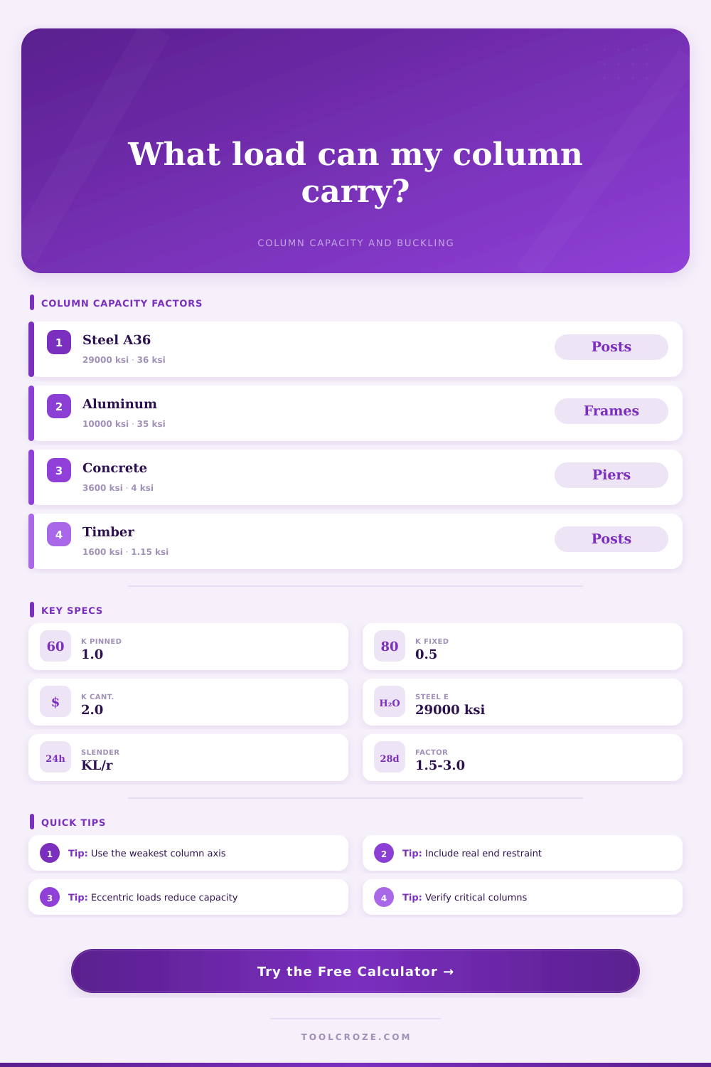
| Structural steel A36 | 29,000 ksi | 36 ksi yield | Posts, pipe columns, HSS frames |
| Structural steel Grade 50 | 29,000 ksi | 50 ksi yield | High strength braced frames |
| Aluminum 6061-T6 | 10,000 ksi | 35 ksi yield | Machine frames and light structures |
| Concrete 4 ksi | 3,600 ksi | 4 ksi compression | Piers and short compression members |
| No. 2 timber post | 1,600 ksi | 1.15 ksi compression | Decks, porches, sheds, temporary supports |
| Reinforced masonry | 1,350 ksi | 2 ksi compression | Pilasters and wall columns |
🔗End Condition K Reference
| End Condition | K Factor | Effective Length | Capacity Effect |
|---|---|---|---|
| Fixed - fixed | 0.5 | 0.5L | Highest buckling resistance |
| Fixed - pinned | 0.7 | 0.7L | Strong restraint at one end |
| Pinned - pinned | 1.0 | 1.0L | Common conservative assumption |
| Sway frame | 1.2+ | 1.2L+ | Lower capacity in flexible frames |
| Fixed - free | 2.0 | 2.0L | Cantilever columns buckle easily |
▣Section Shape Reference
| Shape | Size Inputs | Weak Axis Rule | Best Use |
|---|---|---|---|
| Solid rectangular | Width and depth | Lower of Ix or Iy | Timber, concrete, bar columns |
| Solid square | Width only | Same both directions | Posts and compact piers |
| Solid round | Diameter only | Same all directions | Concrete piers and rods |
| Round pipe | Outer diameter and wall | Same all directions | Steel pipe and aluminum tube |
| Rectangular HSS | Width, depth, wall | Lower hollow inertia | Frames, stands, braced posts |
📊Slenderness and Demand Guide
| Check | Range | Meaning | Calculator Response |
|---|---|---|---|
| Stocky column | KL/r < 50 | Yield or crushing likely controls | Compare stress and squash load |
| Intermediate column | KL/r 50-120 | Both strength and buckling matter | Use lower allowable capacity |
| Slender column | KL/r > 120 | Euler buckling often controls | Review bracing and effective length |
| Service demand | Ratio < 0.80 | Good preliminary margin | Usually acceptable for screening |
| High demand | Ratio > 1.00 | Applied load exceeds allowance | Increase section or reduce length |
📌Preset Scenario Guide
| Preset | Section | Material | Typical Check |
|---|---|---|---|
| Steel HSS Shop Post | 4 x 4 x 1/4 HSS | A36 steel | Moderate braced axial load |
| 6x6 Timber Porch Post | 5.5 x 5.5 solid | No. 2 timber | Short residential compression |
| Round Concrete Pier | 12 in diameter | 4 ksi concrete | Stocky pier capacity |
| Aluminum Tube Frame | 3 x 3 x 1/4 HSS | 6061-T6 aluminum | Light frame buckling |
| Tall Light Pipe Support | 3 in pipe | Grade 50 steel | Slenderness-sensitive post |
💡Column Capacity Tips
Consider how a deck post will bow under load or a porch sag at its joints. Columns both bear down and hold their own against twist and buckling. Restraint, and even geometry, make all the difference between failure and safety. It’s about slenderness and leverage. It is a matter of calculation that most builders do instinctively yet infrequently. After setting the boundary conditions and section, the calculator does math for you. No more looking it up in codes or doing integrals by hand, and that saves you time.
First, you select your material. Concrete, timber and steel don’t compress in the same way. Timber can buckle or crush unexpectedly, while steel yield in predictable ways. Next, you describe the dimension and shape. A square shaped post resist force in every direction. But if you use a rectangular beam as a column, the weak axis of that beam buckles first. That’s a mistake people make a lot. They size to the strong axis and forget about the weak axis, the tool calculates slenderness on the weak axis. So now you aren’t designing for something you’ll never recieve.
How to Use the Column Calculator
The trick comes in calculation of effective length. That’s where all engineering occurs. A column that is fixed into a foundation is not more the same as a column that is pinned both top and bottom. That restraint is captured by the K factor. Using a fixed connection where there is actualy a loose connection will cause math to be wrong. A cantilever column with a K factor of 2 doubles its effective length. It quarters its capacity to buckle. That’s a penalty paid for lack of lateral support. What are the actual connections on site? Are they welded, bolted, resting on a plate? Adjust the factor here based off reality. The calculator allows for this.
Eccentricity cause bending in a compression member. Loads aren’t centered. An offset from the centerline of a beam coming off one side of a post introduce eccentricity, which multiplies the stress since it’s combining bending moment and axial compression. That’s what the tool does: calculates total stress. Offsetting the load one inch will make big difference in capacity. It’s just a tiny bit of geometry that matters more then anything.
Safety factors provide margin for error. You choose a factor that’s appropriate to the risk (consequences if the design fails) and your confidence in the factor. You might use higher factor for a major structural post than for a temporary formwork column. The resistance factor account for material variability. Steel is more consistent whereas timber has knots and concrete contain voids. The output provides you with a demand ratio. Is this below one based off your selected safety factor? Then the column is OK. Is it greater than one? The column is overloaded. It will fail.
Looks don’t matter. Geometry trumps material selection: The same thin column of steel will buckle under less load than a fat pier made from concrete. The real governor? Slenderness ratio. The tables of reference show the tradeoff between strength and stiffness of various materials. Steel yields predictably, and while aluminum is lightweight and flexible, it buckles earlier then steel of the same shape. Aluminum is light but flexible, meaning it buckles earlier than steel of the same shape. Knowing the tradeoffs lets you select proper member for the job.
This is not a definitive tool for construction drawings. This is meant as a prescreening tool that will be used to determine if something is possible prior to contacting an engineer. It does flag dangerous levels of eccentricity and slenderness pretty fast. But there are other things like seismic forces and wind loads in actual buildings. Connection complexity can not be captured by one number alone. Use this as a guide to getting the size correct. Leave the details to the pros, you just want to make sure the column stays up straight. You should of checked your math too.