Pneumatic Cylinder Weight Lifting Capacity Calculator
Estimate cylinder extend force, retract force, safe lifting capacity, required pressure, air volume per stroke, and compressor demand from bore, rod, pressure, stroke, orientation, friction, and load factor.
📌Pneumatic Cylinder Presets
⚙Cylinder and Load Inputs
Pneumatic Cylinder Lifting Results
📊Cylinder Spec Snapshot
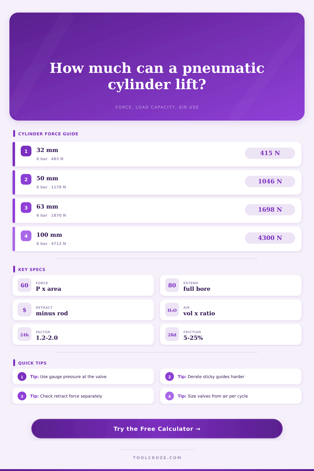
📐Common Bore Force Reference
| Bore size | Area | Extend at 6 bar / 87 psi | Typical rod and retract note |
|---|---|---|---|
| 25 mm / 1 in | 491 mm² / 0.76 in² | About 295 N / 66 lb | 10 mm rod leaves about 84% retract area |
| 32 mm / 1.25 in | 804 mm² / 1.25 in² | About 483 N / 109 lb | 12 mm rod leaves about 86% retract area |
| 50 mm / 2 in | 1963 mm² / 3.04 in² | About 1178 N / 265 lb | 20 mm rod leaves about 84% retract area |
| 63 mm / 2.5 in | 3117 mm² / 4.83 in² | About 1870 N / 421 lb | 20 mm rod leaves about 90% retract area |
| 80 mm / 3.125 in | 5027 mm² / 7.79 in² | About 3016 N / 678 lb | 25 mm rod leaves about 90% retract area |
| 100 mm / 4 in | 7854 mm² / 12.17 in² | About 4712 N / 1059 lb | 32 mm rod leaves about 90% retract area |
🔧Preset Cylinder Spec Grid
| Preset cylinder | Bore x rod x stroke | Common pressure | Typical use check |
|---|---|---|---|
| ISO 25 x 50 mini picker | 25 x 10 x 50 mm | 6 bar | Small pick head or ejector stroke |
| ISO 32 x 100 lift arm | 32 x 12 x 100 mm | 6 bar | Light guided vertical lift |
| ISO 50 x 200 gate assist | 50 x 20 x 200 mm | 6 bar | Gate, chute, or guarded slide |
| ISO 80 x 300 tilt table | 80 x 25 x 300 mm | 6 bar | Fixture lift with angled linkage |
| 1.5 in x 4 in clamp | 1.5 x 0.625 x 4 in | 80 psi | Clamp, press pad, or stop cylinder |
| 3 in x 8 in tilt fixture | 3 x 1 x 8 in | 90 psi | Heavy push or tilt assist |
🧭Orientation and Factor Reference
| Motion condition | Gravity share | Friction range | Load factor suggestion |
|---|---|---|---|
| Vertical lift straight up | 1.00 x weight | 10% to 25% | 1.25 to 2.00 for lifting |
| 45 degree guided incline | 0.71 x weight | 8% to 20% | 1.25 to 1.50 for sticky guides |
| Horizontal slide on rails | 0.20 x weight model | 5% to 20% | 1.10 to 1.50 depending start load |
| Balanced linkage or rolling cart | 0.10 x weight model | 3% to 12% | 1.10 to 1.25 when well guided |
🌬Air Volume Reference
| Cylinder size | Stroke volume | Free air at 6 bar | 10 cycles per minute guide |
|---|---|---|---|
| 32 mm x 100 mm double acting | 80 cm³ extend plus 69 cm³ retract | About 1.04 L per cycle | About 10.4 L/min free air |
| 50 mm x 200 mm double acting | 393 cm³ extend plus 330 cm³ retract | About 5.06 L per cycle | About 50.6 L/min free air |
| 80 mm x 300 mm double acting | 1508 cm³ extend plus 1361 cm³ retract | About 20.1 L per cycle | About 201 L/min free air |
| 2 in x 6 in double acting | 18.9 in³ extend plus 17.0 in³ retract | About 1.84 scf per cycle at 80 psi | About 18.4 scfm at 10 cpm |
💡Pneumatic Lifting Tips
Pneumatic systems has warning labels about stored energy and crushing hazards. To some, this is boilerplate legalese. To others, this is the moment they see their cylinder won’t budge a logical payload. And no, it’s not that pneumatic physics are wrong. Rather, it’s those unseen losses along the line that reduce power by the time it meets the part. Perhaps your cylinder is rated for a thousand Newtons but outputs just six hundred, thats because of friction, seals and geometry of lift.
Input the dimensions and the calculator does the number crunching. No more guessing at conversions and coefficients. Engineering mean knowing how much of that raw potential the tool will use up.
Why Pneumatic Cylinders Lose Power
The first trap is assuming bore size alone determine everything. It is a fifty millimeter cylinder. They look at it and think it lifts the same amount of weight no matter which way you orient it. But gravity isn’t affected by air pressure.
When you lift it straight up you are fighting entire weight of whatever’s attached. On a forty-five degree incline you are only fighting about seventy-one percent of that weight. The remaining weight are absorbed by rails or linkages. That’s where orientation comes into play as an input. It changes the effective load, not the output of the cylinder. You have to understand how much weight your air is moving as a portion of total.
Another aspect is the rod. You would think it is a small thing. Piston rods takes up room in the cylinder on the retract side. That means there’s less surface area for air to push on while retracting. Because the extend force is always greater than the retract force, your design may rely on retraction to pull a heavy component, which can cause the cylinder to stall.
The calculator automaticly takes that into account. It reduces the bore area by the area of the rod. So it’s a small geometric penalty but it adds up fast with high loads.
Pneumatic efficiency is affected by friction. Drag exists in well-lubricated guides. Side-loading, misaligned bearings and sticky seals can rob up to 25% of available power. You can add an allowance for friction to the calculator. Zero equals no resistance. Doesn’t happen. A realistic margin for friction will keep your actuator from failing. Without a realistic friction margin, your actuator might end up humming loudly and moving exactly nowhere.
Designers trip over air consumption. Long strokes and big bores requires high volumes. If you do ten cycles a minute, you need a compressor that will keep up. The tool calculates free air demand per cycle. Size it wrong and you get it right on force but starve it for flow. The result is sluggish movement.
When you need it most pressure drop kills lifting capacity. So what’s the safety net? The safety net is called the load factor. It’s the multiple by which you don’t run your cylinder to capacity. For normal automation, a load factor of 1.25 is standard. It leaves some margin for unexpected jams, wear and pressure spikes. For heavier items or if there is an impact risk, make it two. That means a bigger cylinder. That’s buying you reliability.
Balance. Balance is needed in pneumatic design. If more force, then less air. If more safety margin, then less force. There is no magic. You can have all three but only at high cost. Design for a good cylinder that doesn’t blow a lot of air while maintaining enough safety margin to prevent failure. Use numbers. Use your real-world common sense to finish the design.
What looks like force on paper isn’t what it’s going to feel like at the end of the rod. Never assume the working direction is actualy the working direction. Never assume that the rod will cause a loss of effective area. And never forget about friction. That’s the difference between smooth operation and a stalled machine.