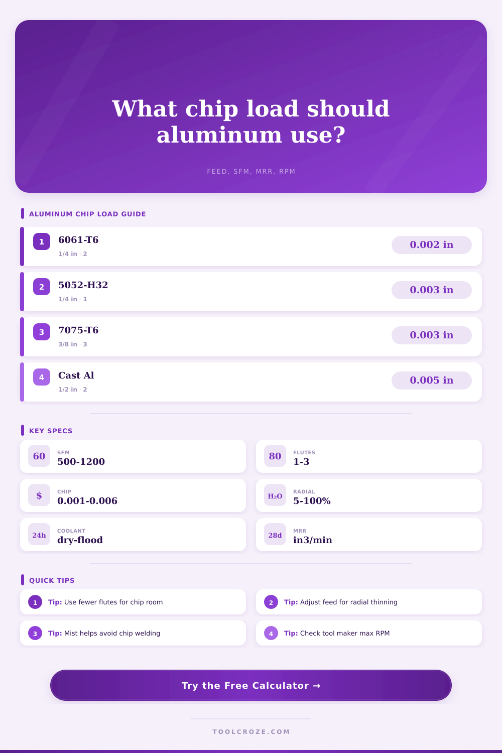
Chip Load Calculator Aluminum
Estimate aluminum milling and router feeds from alloy, cutter diameter, flutes, RPM, feed rate, radial engagement, axial depth, chip thinning, coolant, MRR, and SFM.
⚙Aluminum Presets
📏Inputs
Aluminum Feed Results
🔧Alloy and Cutter Grid
📊Aluminum Alloy Reference
| Alloy | Machining Behavior | Carbide SFM Range | Chip Load Factor |
|---|---|---|---|
| 6061-T6 | Balanced, free machining, predictable chips | 600-1000 SFM | 1.00 baseline |
| 6063 | Softer extrusion alloy, can smear if rubbed | 500-850 SFM | 0.92 factor |
| 5052-H32 | Gummy sheet alloy, needs sharp edges and lube | 450-800 SFM | 0.86 factor |
| 5083 | Marine plate, tougher than 5052 | 450-750 SFM | 0.84 factor |
| 2024-T3 | Strong aircraft alloy, good chip formation | 550-900 SFM | 0.94 factor |
| 7075-T6 | High strength, machines cleanly when rigid | 550-950 SFM | 0.96 factor |
| MIC-6 plate | Cast tooling plate, stable and abrasive spots possible | 500-850 SFM | 0.90 factor |
| Cast aluminum | Varies by silicon content, listen for chatter | 450-800 SFM | 0.88 factor |
⚙Cutter Diameter Chip Load Table
| Cutter Diameter | Light Finish Chip | General Chip | Aggressive Rough Chip |
|---|---|---|---|
| 1/8 in or 3 mm | 0.0004-0.0008 in/tooth | 0.0008-0.0014 in/tooth | 0.0014-0.0020 in/tooth |
| 3/16 in or 5 mm | 0.0007-0.0012 in/tooth | 0.0012-0.0020 in/tooth | 0.0020-0.0030 in/tooth |
| 1/4 in or 6 mm | 0.0010-0.0018 in/tooth | 0.0018-0.0030 in/tooth | 0.0030-0.0042 in/tooth |
| 3/8 in or 10 mm | 0.0015-0.0025 in/tooth | 0.0025-0.0042 in/tooth | 0.0042-0.0060 in/tooth |
| 1/2 in or 12 mm | 0.0020-0.0032 in/tooth | 0.0032-0.0055 in/tooth | 0.0055-0.0080 in/tooth |
| 3/4 in or 19 mm | 0.0030-0.0048 in/tooth | 0.0048-0.0075 in/tooth | 0.0075-0.0100 in/tooth |
📈Engagement and Chip Thinning Table
| Radial Engagement | Chip Thickness Factor | Feed Multiplier | Use Case |
|---|---|---|---|
| 5% of diameter | 0.44 of programmed chip | 2.29x | Very light adaptive cleanup |
| 10% of diameter | 0.60 of programmed chip | 1.67x | Common adaptive roughing |
| 20% of diameter | 0.80 of programmed chip | 1.25x | Fast roughing with chip room |
| 30% of diameter | 0.92 of programmed chip | 1.09x | Profile or pocket wall clearing |
| 50% of diameter | 1.00 of programmed chip | 1.00x | Half-width side milling |
| 100% of diameter | 1.00 of programmed chip | 1.00x | Full slot, watch chip evacuation |
🛠Router and Mill Setup Reference
| Setup | Typical Cutter | Starting RPM | Starting Feed |
|---|---|---|---|
| CNC router sheet aluminum | 1/8-1/4 in single flute O-bit | 16000-24000 RPM | 35-95 in/min |
| Benchtop CNC mill | 1/4-3/8 in 2 flute carbide | 8000-16000 RPM | 25-90 in/min |
| VMC adaptive roughing | 3/8-1/2 in 3 flute carbide | 6000-14000 RPM | 80-220 in/min |
| Finish wall pass | 2 or 3 flute sharp carbide | 10000-20000 RPM | 20-90 in/min |
| Full slot in plate | 2 flute carbide with air or mist | 7000-16000 RPM | 18-70 in/min |
| Cast tooling plate surfacing | Insert shell mill or large carbide | 3000-9000 RPM | 40-180 in/min |
💡Shop Notes
The sound was right. There’s that particular noise that tells you something ain’t quite right. No, it wasn’t a crash. It was just the familiar high pitch of metal on metal, aluminum on a dulled edge, and then nothing.
Most shop floor disasters starts with a single bad decision about chip load. That’s how most mistakes happen here in the shop. It was a bad call on chip load. You feed the material as quickly as you think you can to get it done, but now the calculator say you’re just rubbing the metal.
How to Machine Aluminum Correctly
This calculator on this page will do those calculations for you. Understand why it happens so you can protect your tool. But aluminum? That’s soft, right? Nope. Aluminum is sticky. Aluminum likes to weld to your cutter.
Feed in too slow and it heat up. Heat causes the aluminum to stick. And now you have a built-up edge. Not good. This not only tears into the tool but kill the surface quality as well.
Too fast and the machine can’t cut it and you’ll get chatter and deflection. To make that work, you has to find where the material shears clean without letting too much heat build up on the tool. Then balance between these two extremes.
What makes the difference here is the alloy. Is it a gummy alloy like 5052 or is it a free-machining, predictable 6061-T6? Each alloy has its own coefficient given by the reference table.
Softer extrusions like 6063 requires less pressure and more speed to keep from smearing. Stronger alloys like 7075 will take more load but require rigidity.
The other variable that is least understood is radial engagement. Radial engagement refers to how far the cutter actualy bites into the material. So if you take a light stepover then your chip is going to be thinner. That’s what we call chip thinning.
If you don’t account for it, then you’re running too slow because your feed per tooth doesn’t match what you have it set for in the program. The calculator automatically adjusts for this. If you are running at ten percent radial engagement, then your actual chip is much thinner than what you think it is from your settings. To compensate for this, you need to feed it way more which keeps your cutting edge sharp so it doesn’t rub against itself.
Many people fails to account for this. They ask me all the time why do I get such a bad finish? Or why does my tool keep wearing out on me? It’s not the tool. It’s the math.
The geometry of the cutter. The geometry of the cutter make a big difference. The fewer flutes, the more space available for chips to exit. Aluminum produces longer, continuous chips. These tend to plug up fast. Single- or two-flute O-bits provides a direct path for these chips to evacuate during the cut.
When working with aluminum, four-flute mills is not good unless they have polished flutes and an aggressive helix angle. That is why the interface includes tool style selection. Faster cutting happens on polished carbide as it has less friction. Coatings also help, but if your chip doesn’t have space to evacuate then no coating will help.
You should also consider coolant. Flood coolant is best. But lots of shops goes dry or opt for an air blast. Your choice of coolant affects the conservatism factor that’s built into the calculator.
If you’re dry cutting, you’ll need to slow down or back off on feed to deal with the heat. A small thing like a wax stick or a simple mist will help move chips better and result in a better surface finish. As the chip forms, your lubricating the chip.
Stickout affects the results as well as depth of cut. The longer the stickout, the more flex on the tool. Under load it will deflect. That decreases the chip load and increases chatter. Feed recommendations from the calculator account for stickout, giving you a realistic feed.
You should of decrease the load if you’re trying to go deep into a pocket. Take several shallow passes instead of one deep, risky pass. Remember, this is only a start. The numbers aren’t law. Listen to the machine.
If the pitch changes, it doesn’t sound right. Are the chips thick and curled? Good deal. Blue? Too much heat. It is important to get close with the tool, then use your eyes and ears to refine.
Aluminum machining is as much art as science, more about rhythm than raw strength. Get those chips flowing. Reduce the heat. Let the tool do its thing. A healthy mill sounds like a steady, low hum. Any other sound means trouble.