Rebar Strength Calculator
Estimate tensile yield capacity from bar size, count, grade, As, development reduction, load factor, spacing, layers, and steel ratio.
Rebar Strength Results
| Bar size | Diameter | Area | Grade 60 yield per bar | Typical structural use |
|---|---|---|---|---|
| #3 / 10M | 0.375 in / 9.5 mm | 0.11 in² / 71 mm² | 6.6 kips / 29 kN | Stirrups, light slabs, ties |
| #4 / 13M | 0.500 in / 12.7 mm | 0.20 in² / 129 mm² | 12.0 kips / 53 kN | Slabs, walls, small beams |
| #5 / 16M | 0.625 in / 15.9 mm | 0.31 in² / 200 mm² | 18.6 kips / 83 kN | Beams, footings, mats |
| #6 / 19M | 0.750 in / 19.1 mm | 0.44 in² / 284 mm² | 26.4 kips / 117 kN | Beams, columns, walls |
| #7 / 22M | 0.875 in / 22.2 mm | 0.60 in² / 387 mm² | 36.0 kips / 160 kN | Grade beams, caps, transfer steel |
| #8 / 25M | 1.000 in / 25.4 mm | 0.79 in² / 510 mm² | 47.4 kips / 211 kN | Heavy beams, bridge caps, mats |
| #9 / 29M | 1.128 in / 28.7 mm | 1.00 in² / 645 mm² | 60.0 kips / 267 kN | Deep beams, foundations |
| #10 / 32M | 1.270 in / 32.3 mm | 1.27 in² / 819 mm² | 76.2 kips / 339 kN | Transfer girders, piers |
| #11 / 36M | 1.410 in / 35.8 mm | 1.56 in² / 1006 mm² | 93.6 kips / 416 kN | Very heavy reinforcement groups |
| Grade option | Yield strength | Metric equivalent | Common spec context | Calculator note |
|---|---|---|---|---|
| Grade 40 | 40 ksi | 280 MPa | Older or light-duty reinforcement | Lower strength, easier bend demand |
| Grade 60 | 60 ksi | 420 MPa | Common ASTM A615 / A706 design basis | Default for many US concrete designs |
| Grade 75 | 75 ksi | 520 MPa | Heavy bars and higher demand zones | Check development length closely |
| Grade 80 | 80 ksi | 550 MPa | High-strength reinforcing steel | Often needs stricter detailing checks |
| Grade 100 | 100 ksi | 690 MPa | Special high-strength reinforcement | Use only where permitted by design code |
| Check | Input used | Typical target | Warning sign | Why it matters |
|---|---|---|---|---|
| Clear spacing | Spacing minus bar diameter | At least 1 bar diameter or about 1 in | Bars nearly touching | Concrete must flow around steel |
| Bars per layer | Count divided by layers | Reasonable fit within width | More bars than width can place | Congestion can reduce real capacity |
| Steel ratio | As divided by b times d | Often about 0.2% to 4% | Very low or very high ratio | Flags under-reinforcement or congestion |
| Development reduction | Selected development factor | 1.00 when fully developed | 0.70 or lower | Bar strength may not be fully mobilized |
| Load factor | Demand multiplier | Project-specific design combination | Demand ratio above 1.00 | Shows when factored demand exceeds capacity |
| Preset | Bars and grade | Width and depth | Development | Use case |
|---|---|---|---|---|
| 4 #5 Beam Bottom Bars | 4 bars, Grade 60 | 12 in by 20 in | Full | Typical reinforced beam tension steel |
| 6 #8 Bridge Cap Tension | 6 bars, Grade 60 | 30 in by 32 in | Full | Heavy cap beam positive or negative steel |
| #4 Slab Bars at 12 in | 5 bars, Grade 60 | 48 in by 5.5 in | Full | One-way slab strip check |
| 8 #9 Mat Footing Layer | 8 bars, Grade 75 | 48 in by 24 in | Full | Foundation mat or pile cap band |
| 12 #6 Wall Boundary | 12 bars, Grade 60 | 24 in by 18 in | 0.90 | Boundary or collector reinforcement |
| 3 #7 Grade Beam Top | 3 bars, Grade 60 | 14 in by 22 in | Full | Top steel over support |
| 10 #11 Transfer Girder | 10 bars, Grade 80 | 42 in by 48 in | 0.90 | Large transfer girder tension group |
| Metric 6 N20 Beam Bars | 6 bars, 420 MPa | 300 mm by 520 mm | Full | Metric beam design check |
| Metric N16 Slab Strip | 6 bars, 500 MPa class | 1000 mm by 140 mm | Full | Metric slab strip reinforcement |
| Epoxy Short Development | 5 bars, Grade 60 | 18 in by 24 in | 0.70 | Conservative short embedment case |
Steel stretches well. Concrete doesn’t. Steel holds concrete in place. And concrete crack when under tension. Together this combination lets today’s buildings exist.
We want the steel to stretch and warn us before building goes down. That’s where our calculator comes into play. It do all of the math for you. All you have to do is determine if design works.
How to Use the Rebar Calculator
So first off let’s talk grade and area. Area is total amount of steel in the section, and that is what will determine how much force it can take. There is approximately 0.31 square inches of steel in a #5 bar. So if there are four bars that’s about 1.24 square inches. Multiply that by the steel yield strength (typically 60 ksi for Grade 60 reinforcement) and you’ve got yourself a number for nominal capacity.
It all sounds simple enough until we throw in real world (development length causes some friction). How long should the bar develop? How far does it need to be embedded into concrete to achieve greatest strength? How will this affect development length if I cut it shorter then required? What happens when the bar pulls out before it yields? In this case, the tool provide a reduction factor so that you can input a reduced number based off your conditions. Maybe there’s a congested corner or a short lap splice and as a result, the steel won’t develop to its potential. In this case, it may only develop to say 80 percent or 70 percent of what it could.
This reduction is important because it makes a passing design fail, yet doesn’t alter bar count. A small detail, yes, but an important one.
Spacing and layering also make things more complicated. If you make your beam too narrow, you might be able to squeeze 12 #6 bars inside it, but they’ll crowd each other. And when bars is crowded together, concrete doesn’t flow well around them, which means there won’t be as good a bond between the bar and surrounding concrete.
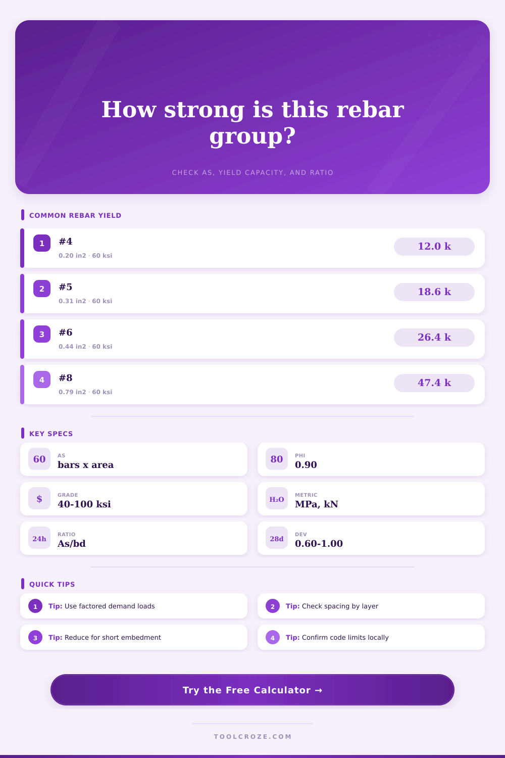
The picture at the top of this page contains a reference table that helps you visualize common bar sizes. By looking at both diameter and area size, you’ll be able to see why a #8 bar isn’t merely a bit larger than a #7 bar. It’s quite a step up in diameter, meaning that moving from a #7 to an #8 is a significant jump that affects how many fit in a layer.
Another number to monitor is the steel ratio. It is called that because it is the area of steel divided by width of the member times the effective depth. There are code limits for this ratio. If you have too much steel, the concrete will crush before yielding; that’s a brittle failure, not good. If there is too little steel, the beam fail abruptly and catastrophically. Ductile failure where the steel stretch and lets you know something is wrong before the building falls down is what you want. The calculator automaticly checks this ratio and reports back whether you are in the safe zone or not.
The design also accounts for load factors. When designing for structures, it’s not about designing for an average load but designing for worst case. For example, you can specify live loads with a 1.6 load factor. That means if your building was completely filled with people, snow and furnitures, the steel would have room to spare. And that’s why engineers are careful; it creates a safety buffer.
The Presets are helpful to get you started. For example, if you are measuring a standard beam it’s going to have a 4 #5 as a preset. The huge force of something like a transfer girder is reflected in a 10 #11. They’re not magic, but rather a starting point. Then you compare the inputs with what’s on your set of drawings for your specific project. The tool will give you the numbers and you’ll use your judgment.
In short, how strong is rebar? That’s a question of faith. It is faith that concrete will support the steel and faith that the steel will support the load. Those two points are connected by the math. And the math says: if your demand ratio doesn’t exceed 1.0, then you’re good to go. If it does, then it’s time for some rethinking.
It’s a straightforward equation. One that could of had major implications. You trust the concrete to hold the steel. The steel supports the load.