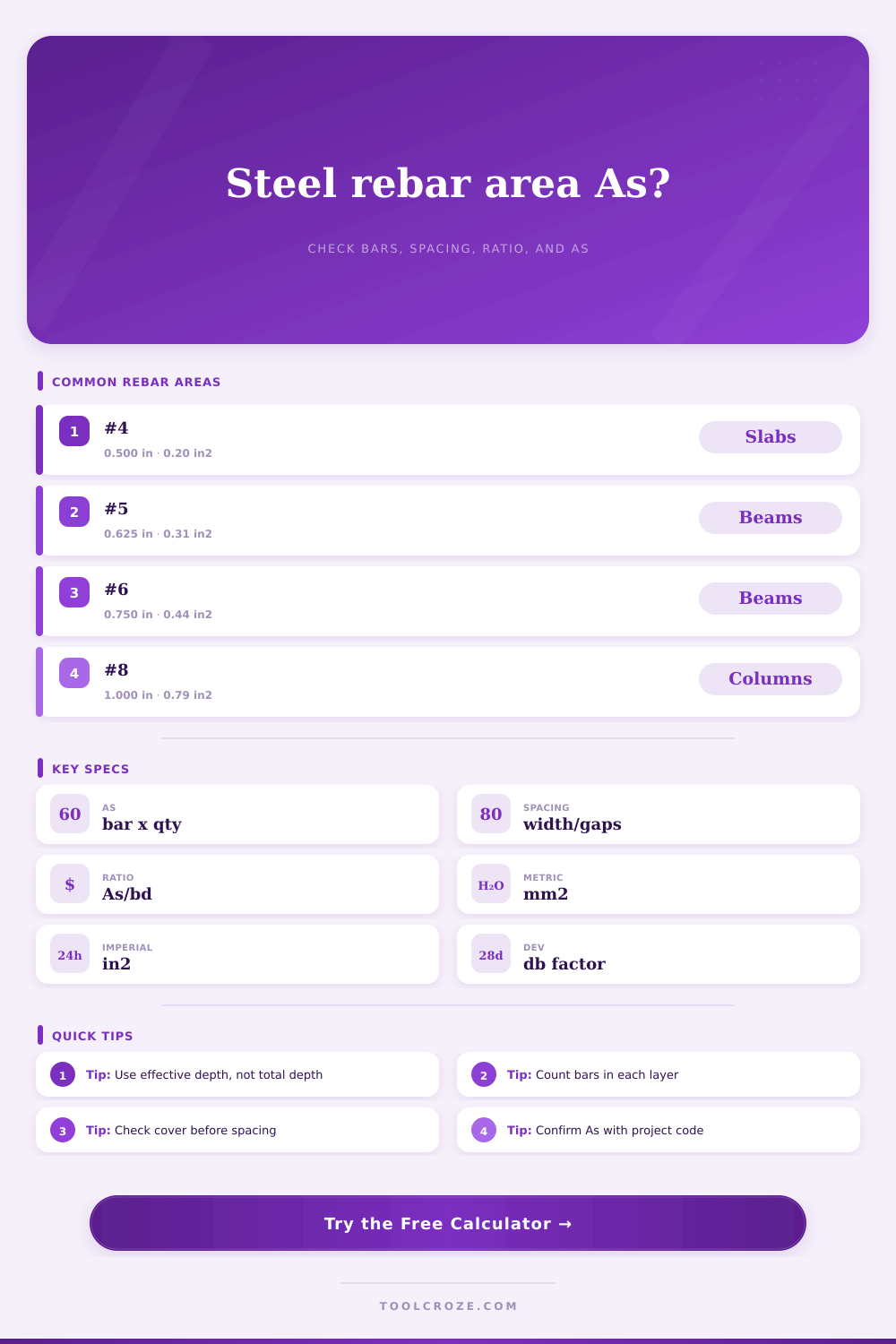
Area of Steel Rebar Calculator
Calculate reinforcing steel area As from bar size, count, spacing, strip width, and layers, then compare provided steel against required As and development length.
📌Real Beam, Slab, and Column Presets
⚙Rebar Area Inputs
Reinforcing Steel Area Results
🧱Common Bar Area Spec Grid
📊US Rebar Size Reference
| US bar | Nominal diameter | Area | Approx metric area |
|---|---|---|---|
| #3 | 0.375 in | 0.11 in² | 71 mm² |
| #4 | 0.500 in | 0.20 in² | 129 mm² |
| #5 | 0.625 in | 0.31 in² | 199 mm² |
| #6 | 0.750 in | 0.44 in² | 284 mm² |
| #7 | 0.875 in | 0.60 in² | 387 mm² |
| #8 | 1.000 in | 0.79 in² | 510 mm² |
| #9 | 1.128 in | 1.00 in² | 645 mm² |
| #10 | 1.270 in | 1.27 in² | 819 mm² |
| #11 | 1.410 in | 1.56 in² | 1006 mm² |
📏Metric Rebar Size Reference
| Metric bar | Nominal diameter | Area | Approx US area |
|---|---|---|---|
| 10M | 11.3 mm | 100 mm² | 0.155 in² |
| 15M | 16.0 mm | 200 mm² | 0.310 in² |
| 20M | 19.5 mm | 300 mm² | 0.465 in² |
| 25M | 25.2 mm | 500 mm² | 0.775 in² |
| 30M | 29.9 mm | 700 mm² | 1.085 in² |
| 35M | 35.7 mm | 1000 mm² | 1.550 in² |
| 45M | 43.7 mm | 1500 mm² | 2.325 in² |
| 55M | 56.4 mm | 2500 mm² | 3.875 in² |
🗂Layout and Ratio Reference
| Check | Useful formula | Typical use | Calculator output |
|---|---|---|---|
| Total As | Bar area x bars x layers | Beams, columns, piers | Provided As card |
| Spacing As | Bar area x 1000 / spacing | Slabs and walls per meter | As per meter breakdown |
| Steel ratio | As / (b x d) | Quick reinforcement density check | Steel Ratio card |
| Development | db x selected factor | Anchorage planning indicator | Development card |
| Required margin | (Provided - Required) / Required | Compare schedule to design As | Required vs Provided card |
🏗Preset Scenario Reference
| Preset | Layout | Design strip or member | Primary check |
|---|---|---|---|
| 12 in Beam, 4 #5 | Count | 12 in x 20 in d | Required As margin |
| Slab #4 at 12 in | Spacing | 12 in design strip | As per foot and spacing |
| Column 8 #6 | Count | 18 in column | Gross steel ratio |
| Metric Slab 15M at 200 | Spacing | 1000 mm strip | As per meter and ratio |
💡Calculation Tips
There’s geometry involved in rebar sizing. There is also unit conversion. There is also scheduling. If you know size of a bar, then you know area (pi times radius squared). But the math gets messier out in the field. It goes beyond simple math. That’s where the rebar area calculator on this page come into play. Just input your member sizes and it does the math for you. No need to guess at conversions or coefficients.
It’s not the number crunching that has any real value here. Before you grab a list of bars, consider what you are actualy reinforcing. The input stage is where most people goes wrong. Total depth isn’t the same as effective depth. Sure, you can see slab is eight inches thick. But steel doesn’t sit right on bottom. It’s sitting atop cover blocks and chairs. The steel’s bending capacity depend on how far below compression face the centroid (center) of the steel is. Using the total depth will make your steel look safer then it is. That’s an unsafe illusion. The tool requires effective depth, so it won’t let you make this mistake. It is a tiny input, yet it bear the weight of the structural argument.
Why Using a Rebar Area Calculator Helps You Build Safely
Beyond that, there’s the question of layout. Do you have a bar grid? Are they spaced apart, like for slab floor or wall? Or do you have separate bars, like in a beam? Those are different mental models so you can flip back and forth between them in calculator. For a beam, you’re thinking about counts. There is four number five bars. Got it. On a slab, you’re thinking about spacing. Use number four bars spaced twelve inches on center. That’s a typical spec. Then the tool converts that into an area per meter or per foot. So then you can compare it directly to your design requirement. It connects ideas in your design notes to where things actually go in real world.
Another thing we tend to overlook until things go wrong: Steel ratio. It is nothing more than a fraction: Area of Steel/Area of Concrete. There are reasons codes has min/max ratios. Not enough steel results in concrete cracking abruptly with no prior warning. Excessive steel means failure will be both catastrophic and brittle. The steel ratio is automatically calculated on the fly. It doesn’t say if your design is good; only if it’s plausible. Normal would of been a two percent ratio. Ten percent is a red flag. Something went wrong somewhere in the input assumptions or calculations.
How long should the rebar be? That’s the critical element of how any rebar system work well. All that steel are in place, but without a good anchor, it is nothing more than an expensive ornament. How much do we embed into the concrete so that bar develops its maximum strength? And when will that happen before slipping out from under? We base a fast indicator off that in our calculator: it’s quick but not a test for final proof. It will catch obviousely wrong numbers. If what you’ve got isn’t as long as the necessary development length (based on the simple code factors and bar diameters), then you’re looking at mechanical anchors or hooks. More bar doesn’t help if you don’t have a good anchor.
For quick reference, those tables on page serve their purpose. A job site tent doesn’t contain some strange imperial-to-metric conversion table. But you’ll want to know that a number six bar is about one-half square inch. About a full square inch is a number eight bar. Those are the numbers that exist in an experienced estimators head. They’re the ones memory lets down under pressure. This tool keeps them at our fingertips.
Calculating rebar area is less about geometry than it is about coordination. You’re taking a force diagram and making it a real thing. It sits in the middle of a form with some wet concrete. The calculator does the math for you. It checks that the ratios works out and units are correct. But it can’t check the bar spacing to ensure good concrete flow. It can’t tell if there’s interference between the longitudinal bars and the stirrups. That’s what makes the difference between a theoretical design and an actual building. Make sure the math adds up. Verify the anchors. Always remember the effective depth. The steel works only if it’s placed where it needs to be.