Bolt Circle Chord Length Calculator
Calculate center chord, skipped-hole distance, clear web, required outside diameter, angular spacing, and tolerance range for circular bolt layouts.
Bolt Circle Results
| Bolt Count | Adjacent Chord Multiplier | Skip 2 Multiplier | Opposite or Wide Chord |
|---|---|---|---|
| 3 bolts | 0.8660 x BCD | 0.8660 x BCD | Same as adjacent |
| 4 bolts | 0.7071 x BCD | 1.0000 x BCD | Across circle |
| 5 bolts | 0.5878 x BCD | 0.9511 x BCD | Largest skip is 2 |
| 6 bolts | 0.5000 x BCD | 0.8660 x BCD | 1.0000 x BCD at skip 3 |
| 8 bolts | 0.3827 x BCD | 0.7071 x BCD | 1.0000 x BCD at skip 4 |
| 10 bolts | 0.3090 x BCD | 0.5878 x BCD | 1.0000 x BCD at skip 5 |
| 12 bolts | 0.2588 x BCD | 0.5000 x BCD | 1.0000 x BCD at skip 6 |
| Use Case | Pattern | Typical BCD | Adjacent Center Chord |
|---|---|---|---|
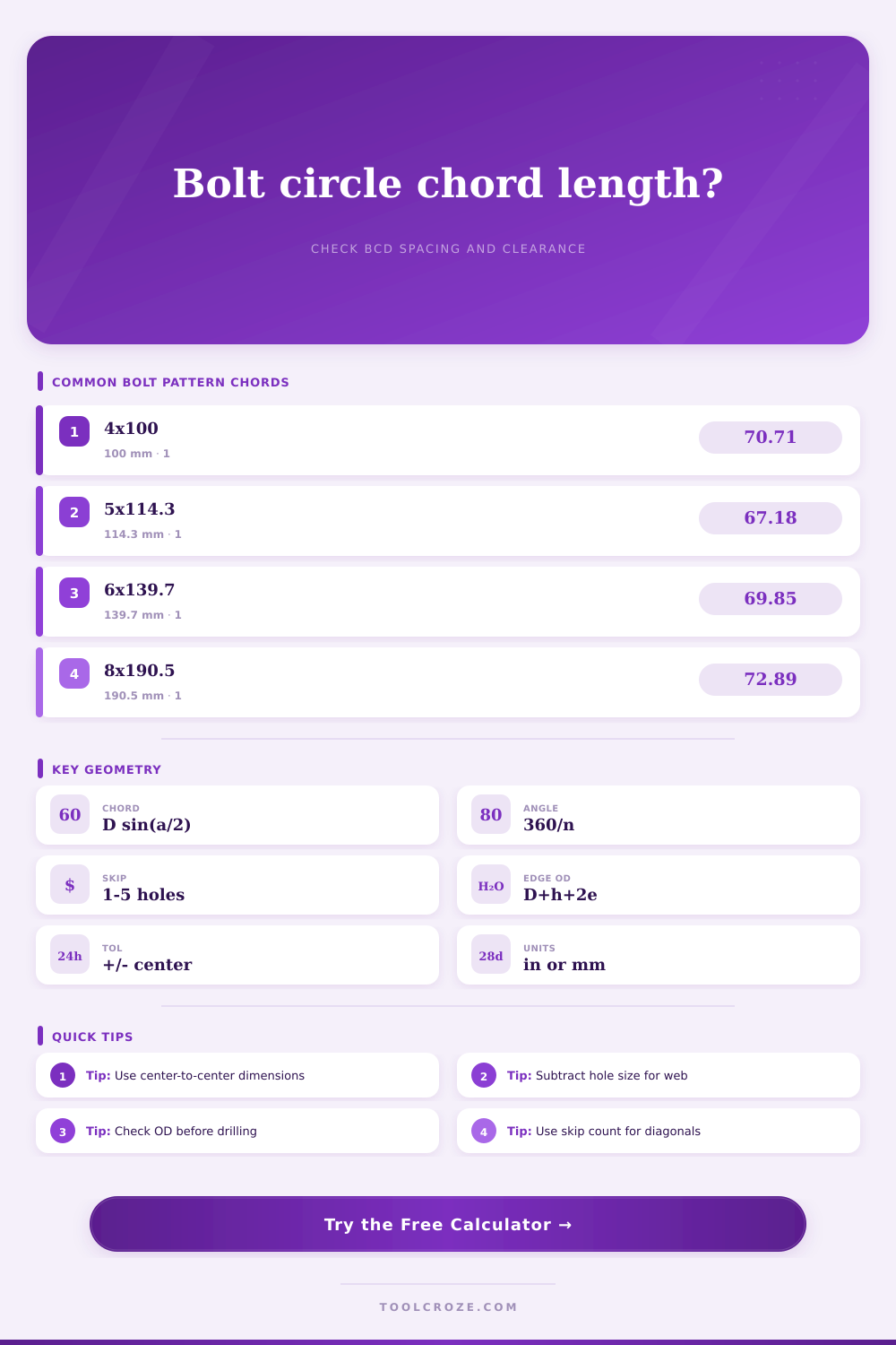
| Compact wheel hub | 4 x 100 | 100.00 mm | 70.71 mm |
| Passenger wheel hub | 5 x 114.3 | 114.30 mm | 67.18 mm |
| Light truck wheel | 6 x 139.7 | 139.70 mm | 69.85 mm |
| 2 inch ASME Class 150 flange | 4 bolt | 120.65 mm | 85.31 mm |
| 4 inch ASME Class 150 flange | 8 bolt | 190.50 mm | 72.89 mm |
| DN100 PN16 metric flange | 8 bolt | 180.00 mm | 68.88 mm |
| Small sprocket carrier | 6 x 100 | 100.00 mm | 50.00 mm |
| Rotary table ring | 12 x 300 | 300.00 mm | 77.65 mm |
| Material or Part | Minimum Edge Rule | Minimum Web Rule | Typical Layout Tolerance |
|---|---|---|---|
| Carbon steel flange | 0.75 x hole diameter | 0.50 x hole diameter | 0.25 to 0.75 mm |
| Stainless steel flange | 0.85 x hole diameter | 0.60 x hole diameter | 0.20 to 0.50 mm |
| Aluminum wheel or hub | 1.00 x hole diameter | 0.75 x hole diameter | 0.10 to 0.30 mm |
| Cast iron sprocket | 1.10 x hole diameter | 0.80 x hole diameter | 0.20 to 0.50 mm |
| Alloy steel carrier | 0.80 x hole diameter | 0.60 x hole diameter | 0.10 to 0.30 mm |
| Engineering plastic plate | 1.50 x hole diameter | 1.00 x hole diameter | 0.25 to 1.00 mm |
| Check | Formula | Use It For | Watch Point |
|---|---|---|---|
| Angular spacing | 360 / bolt count | Indexing plates and rotary tables | Round only after layout |
| Chord length | BCD x sin(angle / 2) | Verifying adjacent or skipped holes | Use degrees consistently |
| Required OD | BCD + hole + 2 x edge | Blank sizing and flange rings | Edge is from hole edge |
| Bore bridge | (BCD - bore - hole) / 2 | Hub pilots and lightening holes | Negative means overlap |
| Coordinate X | R x cos(angle) | CNC, DRO, and layout tables | Apply first-hole offset |
| Coordinate Y | R x sin(angle) | CNC, DRO, and layout tables | Check quadrant signs |
All too often a flange won’t lay down flat or a stubborn hub on the wheel won’t cooperate. Bolts aren’t usually the issue. It’s the hidden geometry joining them together.
A bolt circle isn’t simply a ring of holes. It’s an exact mathematical relationship of distance, angle and diameter. Get the spacing incorrect and everything go bad.
How to Use a Bolt Circle Calculator
The critical piece is called the chord length. That is the straight line between the centers of any two hole. Will your plate be wide enough? Will there be enough metal between the holes to prevent tearing? Will the assembly seal or even rotate properly?
So most folks believe there is just one number. And they think if they know it, the rest will fall into place. Nope. The distance between holes are shorter than the diameter. Web thickness isn’t included either. Four holes spread well apart. Twelve holes on the same diameter pack them in pretty good. On a given diameter, there’s less material for holding fasteners when loaded. That’s the mistake folks make. They don’t pay attention to web thickness till it crack when they go to install it.
To use it, simply enter the diameter and number of bolts then let calculator do the math for you. It calculates the sin values and translates them to actual lengths.
What does that mean in terms of your application? That’s where the next step comes in. What’s the chord length? That’s the straight line distance from one hole to another. And if you missed a hole? Yep, that’s going to change measurement. On a five-bolt pattern, jumping every other hole is a lot different then measuring neighbor to neighbor.
Need to check clearances on a long bolt? Want to confirm a custom adapter fits over existing threads without hitting anything? Ditto.
You should know your materials. Some materials require increased edge distance; aluminum hub versus steel flange, for example. The former is softer and can be deformed. Other materials are brittle, such as cast iron sprocket. Those require ample margin to avoid cracking while under torque.
To address this variability the tool sets tolerances and selects materials that account for it. The tool uses the bolt circle radius, the hole diameter, and your preferred edge distance to compute needed outside diameter so that you don’t cut a blank that’s too short. That last couple of holes won’t be on the brink of the rim.
The real world of the shop floor is a mess. No tool is perfect. There is no such thing as an infinitely precise layout scribe. Adding a tolerance range to your calculations gives you a buffer. Putting a plus or minus number into your math will add a buffer. You’ll be able to see acceptable range of variation in the placement of a hole. This helps you catch mistakes before they are too far gone to use. And yes, when your chord length says 70 millimeters +/-.5mm you’ll know what kind of wiggle room you’ve got to work with. Don’t ignore it and you don’t get parts that look right but don’t quite fit. Slightly misplaced holes add up until the whole circle is thrown off, and it’s painful to correct.
People get confused about whether they are calculating edge-to-edge or center-to-center. The distance between holes measured using calipers is actualy the clear web. It’s NOT talking about the chord; it’s the distance between centers plus radius of both holes. That means your calculation will be consistently shorter if you don’t account for the radius when calculating distances. Not accounting for the offset on the first hole will also cause rotational offsets. To get coordinate outputs that match your physical setup, make sure to set starting angle if your pattern needs a certain clocking position.
There was also a very useful reference table on the page breaking out multipliers for various amounts of bolts. That allows you to quickly determine how far the chord will extend based off the diameter without having to run the math yourself. Say you have a 4 bolt circle in the next picture. The chord would be about 70% of the diameter. In a 6 bolt circle, it’s only 50%. Knowing those kind of ratios makes the geometry easier to visualize. Without a calculator, you can figure out that putting more bolts means they’ll get closer together. Now you can plan what material to use and those numbers help with that too.
So what? A bolt circle is a promise of symmetry. Each hole must match the angle and the radius. The chord length is nothing more than a check of that promise. It is the assurance that the part will perform as intended. Whether that be sealing a pipe joint together or holding a rotor on a spindle.
If you take your time to work out these measurements properly, then you’ll save hours of reworking. You’ll move from a guessing game to a precise engineering exercise. As long as you measure from the center, the numbers won’t lie. You should of checked them twice.