⚙ Morse Taper Calculator
Size MT0 through MT7 tooling, compare measured taper dimensions, estimate seating depth, drawbar contact pressure, and spindle runout sensitivity.
🔧Machine-Tool Presets
📏Morse Taper Inputs
🎯Calculated Results
Morse Taper Results
Calculation Breakdown
🗂Selected MT Spec Comparison
📊MT0-MT7 Standard Dimensions
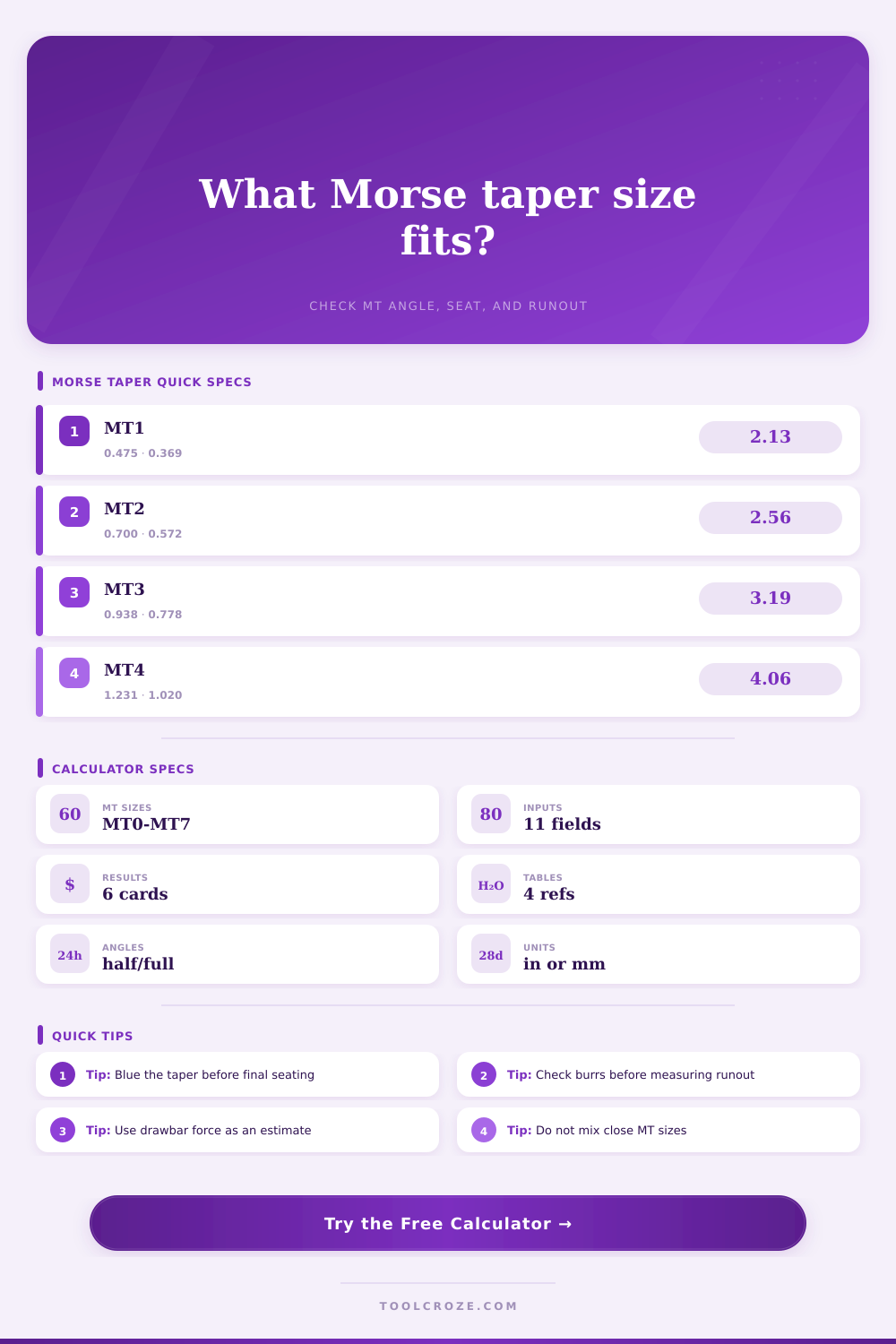
| Morse taper | Large end in | Small end in | Gauge length in | Taper per foot | Half angle |
|---|---|---|---|---|---|
| MT0 | 0.3561 | 0.2520 | 2.00 | 0.6246 | 1.4908° |
| MT1 | 0.4750 | 0.3690 | 2.13 | 0.5986 | 1.4287° |
| MT2 | 0.7000 | 0.5720 | 2.56 | 0.5994 | 1.4307° |
| MT3 | 0.9380 | 0.7780 | 3.19 | 0.6024 | 1.4377° |
| MT4 | 1.2310 | 1.0200 | 4.06 | 0.6233 | 1.4876° |
| MT5 | 1.7480 | 1.4750 | 5.19 | 0.6315 | 1.5073° |
| MT6 | 2.4940 | 2.1160 | 7.25 | 0.6257 | 1.4933° |
| MT7 | 3.2700 | 2.7500 | 10.00 | 0.6240 | 1.4894° |
🧮Formula Reference Table
| Calculated item | Formula | Imperial units | Metric units |
|---|---|---|---|
| Taper per inch | (Dlarge - Dsmall) / L | in/in | mm/mm |
| Taper per foot | taper per inch x 12 | in/ft | shown as in/ft equivalent |
| Half angle | atan((Dlarge - Dsmall) / (2 x L)) | degrees from center | degrees from center |
| Contact area | pi x mean diameter x engaged length / cos(angle) | square inches | square millimeters |
| Tip runout | face TIR x (1 + overhang / engaged length) | in TIR | mm TIR |
⚖Seating And Pressure Planning Grid
| Condition | Typical sign | Calculator field | Shop response |
|---|---|---|---|
| Short contact band | Blue marks only at one end | Contact band below 50% | Inspect burrs, dirt, and taper damage |
| Deep seating | Tool pulls in past witness line | Positive seating movement | Check socket wear and tang clearance |
| Low drawbar force | Adapter frets or slips | Small seating force | Confirm drawbar thread and torque |
| High runout growth | Tip TIR grows with overhang | Long tool tip overhang | Indicate close to taper before blaming tool |
| Mixed taper size | Contact at mouth only | Large/small mismatch | Do not force near-size tapers together |
🔧Common Morse Taper Tooling Cases
| Tooling case | Common MT sizes | Seating check | Runout check |
|---|---|---|---|
| Small drill press chuck arbor | MT1, MT2 | Hand seat plus clean release | Indicate chuck body and test pin |
| Lathe tailstock dead center | MT2, MT3, MT4 | Full blue contact under quill load | Check center point at working extension |
| Reduction sleeve | MT3 to MT2, MT4 to MT3 | Both inner and outer tapers bear | Indicate sleeve bore after seating |
| Drawbar tool holder adapter | MT2, MT3, MT4 | Drawbar tension repeats witness line | Check after tightening, not loose fit |
| Radial drill arbor | MT4, MT5 | Heavy axial load without fretting | Indicate near the drill shank |
| Large lathe center | MT5, MT6, MT7 | Even contact, no galling | Check center at tailstock extension |
💡Morse Taper Tips
This calculator compares Morse taper size, diameter change, angle, seating shift, pressure, and runout sensitivity so machinists can check adapters, centers, arbors, and sleeves.
Machinists gets a particular type of frustrated when they know their tool’s out of round but don’t understand why. They’ve tapped it in on a piece of wood with a wooden mallet, then they’ve cleaned the taper. Then they’ve pulled it down on drawbar until skin on their knuckles went white. And even after all this, the dial indicator still dances around and the part they’re making doesn’t look smooth anymore… More like a topographical map.
Usually the issue isn’t that Morse taper itself is broken. It’s typically because the geometry of the fit changed, too slight for human eyes to see. That calculator allows you to quantify just how big a deal that change was. And what to do about it.
Why Morse Tapers Are Not Working Right
Morse tapers are simple elegant designs that can be difficult to make right. By using conical geometry and friction they create a way to retain tooling without using bolts. This design dates back to the mid 1860s and frankly it just plain works. It is simple, but it is not so simple because there are some tricks to getting it right.
The biggest trick is thinking if something looks like a good fit visually, then it’s mechanically accurate too. So you’ve got that nice blue ring of contact dye around the socket opening and think everything fits perfect. But what happens when the taper inside is worn on its smaller end? It pull into itself more. And not only does it do this, but it pulls the axis off center which magnifies even slight flaw in your tool’s tip.
So when you push your tool down further, or try to pull it up, the calculator walks you through the math of how much that movement will move it axially. That change is what will silently kill your accuracy. Most folks go astray when they try to understand what goes in. Those big and little diameters don’t come from a catalog page randomly. They’re the real world dimensions of the spindle and tool envelope.
And if you’ve got a heavily used spindle, those diameters may be a bit different as they’ve worn or galled. That’s why we let you put in the real-world gauge length and the percent of the taper that is really making contact. If it’s a low contact percentage, that means the tool is only gripping at the very ends, which creates a weak point that flex under load. That’s a weak spot that will flex under load.
From there, the system look at your drawbar force and estimates how much contact pressure you’ll have against the tool. That’s key. Too tight and you can deform the metal and strip the drawbar threads. Not enough and you’ll see slippage and fretting.
There’s also the matter of runout sensitivity. Many times it feels like we trust our gut and don’t think much about how much runout there is at the gauge face. The farther out from the nose of the spindle the error increases due to the physics of leverage. The tool calculates this amplification based off your tool overhang. If you’ve got a small drill bit on a long sleeve or if you’re running a long boring bar, the tip will wander far more then the base. That can save you from blaming the well-aligned spindle or perfectly good tool. You can know that beforehand and focus on setup geometry rather than quality hardware.
They even have a reference table on the page showing the typical sizes from MT0- MT7. It is handy for a quick confirmation, but it really works best with presets to model your specific machine configuration. Whether you’re testing an MT1 watchmakers spindle or a beefy MT4 mill adaptor the procedure is identical.
Before you cut anything in metal, you want to understand how the tool behaves. Thoroughly clean the tapers and look for any burrs which could keep it from sitting all the way down. With the estimated runout and pressure values make a decision as to whether or not your setup will be stable for whatever task you have in mind. Taking a few minutes to confirm the geometry upfront saves hours of rework later.
Controlling what you can see is precision machining, not necessarily having the most expensive machines. The handshake between the tool and the machine is the Morse taper. When that is true and firm, things go smoothly. When it’s off or loose, you are fighting with the machine.
Make the handshake solid using the numbers. Trust the geometry and clean the interface. The tool will hold and the cut will be true.