Taper Per Foot to Degrees Calculator
Convert diametral taper per foot into included angle, side angle, end diameters, compound settings, indicator movement, sine-bar blocks, and lathe tailstock offset.
Calculated Machining Setup
| Taper | Large End | Small End | Length | Taper / Foot | Side Angle |
|---|---|---|---|---|---|
| MT0 | 0.3561 in | 0.2520 in | 2.00 in | 0.6246 in/ft | 1.4908° |
| MT1 | 0.4750 in | 0.3690 in | 2.13 in | 0.5986 in/ft | 1.4287° |
| MT2 | 0.7000 in | 0.5720 in | 2.56 in | 0.5994 in/ft | 1.4307° |
| MT3 | 0.9380 in | 0.7780 in | 3.19 in | 0.6024 in/ft | 1.4377° |
| MT4 | 1.2310 in | 1.0200 in | 4.06 in | 0.6233 in/ft | 1.4876° |
| MT5 | 1.7480 in | 1.4750 in | 5.19 in | 0.6315 in/ft | 1.5073° |
| Standard | Use Case | Taper / Foot | Side Angle | Included Angle |
|---|---|---|---|---|
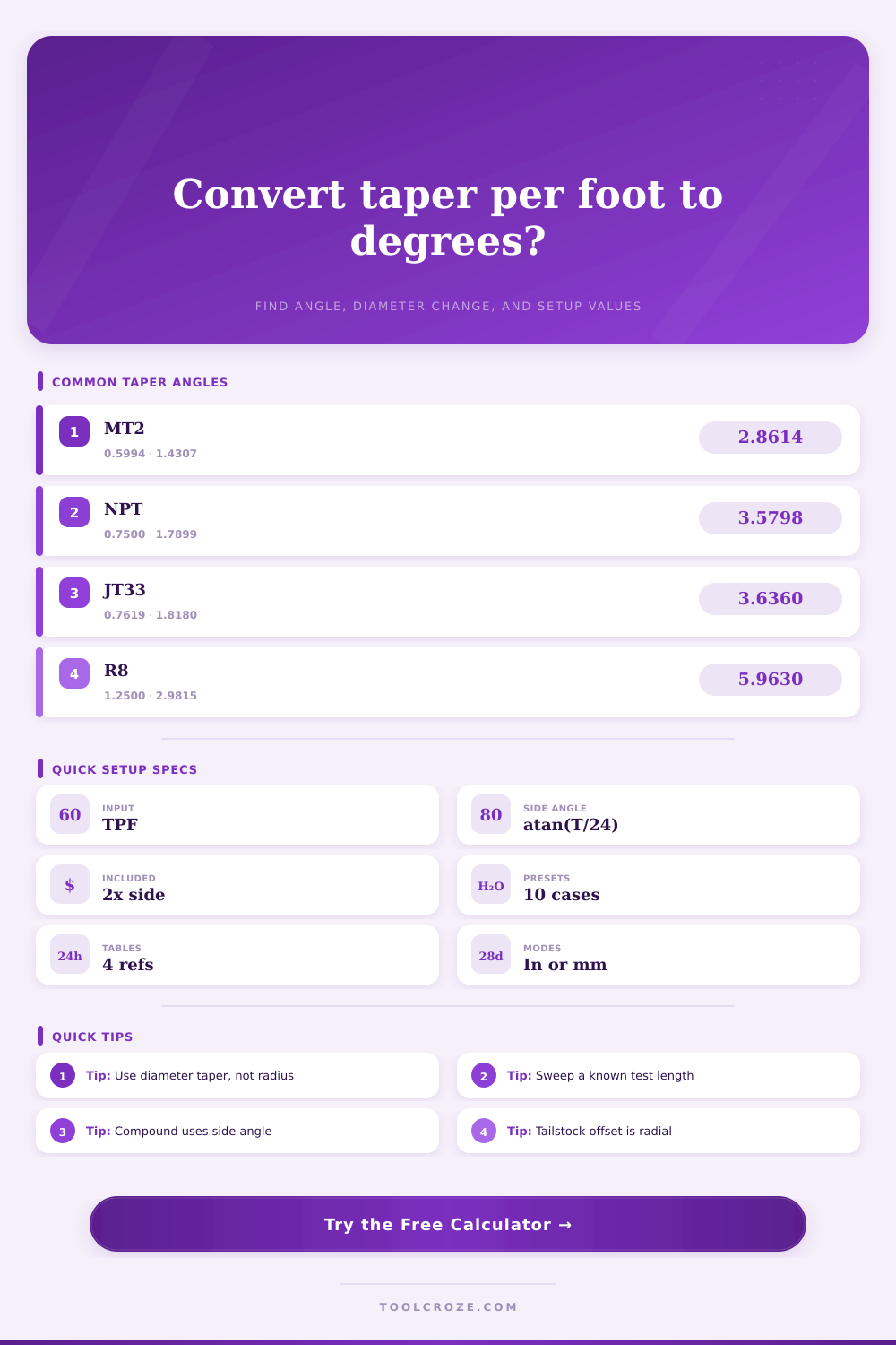
| NPT / NPTF | Pipe thread reaming and gauging | 0.7500 in/ft | 1.7899° | 3.5798° |
| BSPT / Rc | ISO-style tapered pipe threads | 0.7500 in/ft | 1.7899° | 3.5798° |
| Jarno | Machine arbors and test plugs | 0.6000 in/ft | 1.4321° | 2.8642° |
| Brown & Sharpe | Self-holding centers and arbors | about 0.5000 in/ft | 1.1935° | 2.3870° |
| Jacobs JT33 | Drill chuck mounting taper | 0.7619 in/ft | 1.8180° | 3.6360° |
| R8 | Manual mill spindle shank | 1.2500 in/ft | 2.9815° | 5.9630° |
| Output | Formula | Meaning | Machining Use |
|---|---|---|---|
| Side angle | atan(TPF / 24) | Angle from centerline | Set compound slide from spindle axis |
| Included angle | 2 × side angle | Cone angle from side to side | Compare drawings that call included angle |
| Diameter change | TPF × length / 12 | Large diameter minus small diameter | Predict end diameter after turning |
| Tailstock offset | TPF × center distance / 24 | Radial center displacement | Offset tailstock for between-centers taper |
| Indicator change | TPF × sweep / 24 | Radial rise over test sweep | Dial in compound, boring head, or fixture tilt |
| Sine stack | sin(side angle) × roll distance | Height under one sine-bar roll | Set surface grinder, mill fixture, or inspection plate |
| Material / Spec | Finish Allowance | Preferred Check | Shop Note |
|---|---|---|---|
| 12L14 / 1215 steel | 0.0005 to 0.0015 in | Blue fit plus micrometer diameters | Easy finishing, but avoid tearing from a dull point. |
| 4140 prehard | 0.0010 to 0.0020 in | Indicator sweep before final pass | Spring can move the small end; repeat the same final pass pressure. |
| 303 / 304 stainless | 0.0015 to 0.0030 in | Gauge ring, plug, or taper socket contact | Work hardening favors a sharp tool and a positive final cut. |
| 6061-T6 aluminum | 0.0010 to 0.0020 in | Diameter pair and layout blue witness | Thermal growth can mask tenths-level taper corrections. |
| Bearing bronze | 0.0010 to 0.0025 in | Blue fit and soft jaw repeat check | Use light pressure when seating male and female tapers. |
| Pipe thread taper | Gauge-driven, not free allowance | L1 plug or ring gauge position | Angle is only one requirement; pitch diameter controls acceptance. |
On drawings, it might say something like a Morse taper at.5986 inches per foot. To offset your tailstock or set your compound slide, you must turns that linear amount of change into an angular amount. When converting, we makes mistakes. We tend to mix up the side angle and the included angle, that will lead you to a part that doesn’t fit. And before you know it, you’re running around shop floor trying to chase errors.
You input your exact dimensions and let the calculator do the trigonometry. You no longer have to convert the change in diameter into degrees.
How to Use a Taper Calculator
Diametrical taper is measured in diameter per foot. So it tell you what happens to the diameter as it tapers or bulges over a given distance (in our case 12 inches). It doesn’t tell you what happens to the radius.
Half of total included angle is the angle you enter into the machine. Remember that since each side of the cone is cut separately, you are only cutting one side of the cone at a time. To be clear: you want the angle from the center line to the surface. It is not the entire angle across both sides of the object, that’s what confuses most machinists who initialy see these numbers.
How this changes interpretation of set up: On a lathe you rotate the compound slide base to the side angle and the tool runs directly down the length of the taper. The angle doesn’t change.
If you’re turning between centers, you offset the tail stock. Because that’s an offset which is radial, geometry has changed. The offset is based off radius change, not diameter change. The calculator gives you a certain amount of tailstock offset. That offset assume that the full distance between your centers will be used. It doesn’t assume only the length of your tapered section.
If you use the wrong length for your tailstock offset, your taper will be either too steep or to shallow. If you use the wrong length, your taper will be too steep or too shallow. You could of fine tune something that is fundamentally set up wrong.
Aggressiveness of the taper depends on material. Free cutting steel will allow taking light finishes. Then you can go back and check end diameter with a micrometer. It is not like that with stainless steel or any other pre-hardened alloy. There’s no way to tell if the work has been ruined by hardening until it won’t fit.
You need a sharp tool. Use a positive finish cut on these to prevent ripping off the finish.
Tables of references show all the differences between the various standards. Jacobs chucks vs pipe threads is very different. Self-holding machine tapers are much shallower then pipe threads. Pipe threads allow less room for error. There is less leeway in the angle adjustment before the gauge rejects it.
Verification is where theory meets the messy reality of metal. Extreme accuracy can be reached using a sine bar setup. To get the proper side angle, you want to know exactly how tall your block needs to be. That’s where the sine stack comes in from the calculator. Extreme accuracy can be achieved using a sine bar setup. To get the proper side angle, you want to know exactly how tall your block needs to be. That’s where the sine stack comes in from the calculator.
Now you can set up a fixture, or even check a ground taper on the bench. It brings the degrees out of the abstract world and puts them in terms of a real height you can see and measure. That closes the loop between the drawing and the part.
And then there’s the wear and play in the machine tools. That’s why the indicator sweep check has value. By measuring the change radially over a known distance, you can verify the actual taper created by the tooling. It’s independent of the theory angle.
The calculator handles the conversion from taper per foot to degrees for you when setting a tailstock offset. Until you put it into metal, those numbers on the page are nothing but guidance.
Whether you’re dialing in a compound angle for a short bushing or setting a tailstock offset for a long shaft, you want the surfaces to match. The tool gives you the map. Now, you have to drive the machine. Get the angle right. Respect the limits of the material. Check your work before the final pass.
It’s a small detail. It makes the difference between a good part and a perfect fit.