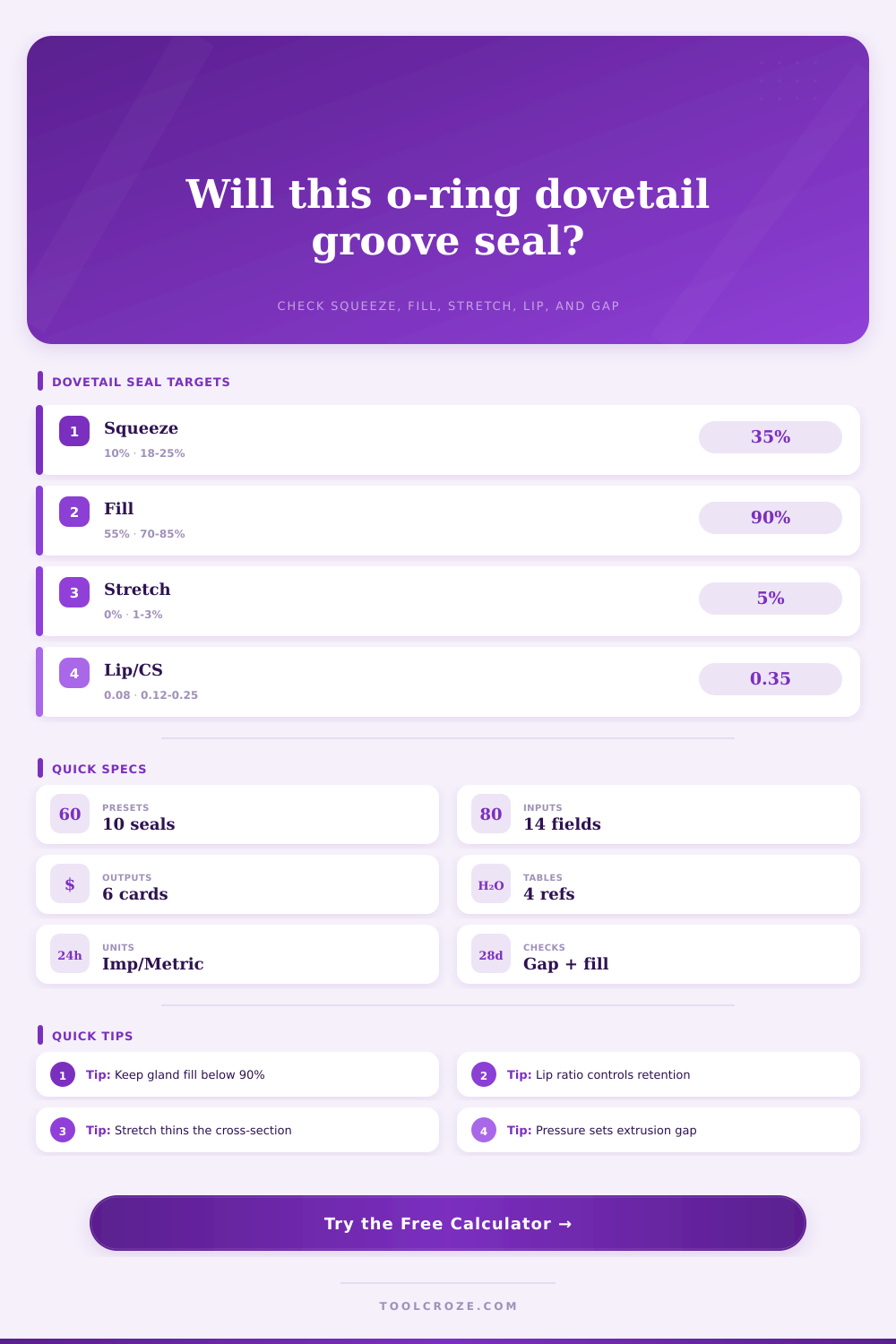
O-Ring Dovetail Groove Design Calculator
Check dovetail retention, squeeze, gland fill, stretch, thermal expansion, fluid swell, and extrusion clearance for captured o-ring grooves.
Calculation breakdown
| Gland type | Squeeze target | Fill target | Stretch target | Design note |
|---|---|---|---|---|
| Static face dovetail | 18% to 30% | 70% to 85% | 0% to 3% | Most captured cover seals land here. |
| Vacuum face dovetail | 20% to 35% | 65% to 82% | 0% to 2% | Extra squeeze helps leak rate, but fill still needs void. |
| Static radial piston | 12% to 22% | 65% to 82% | 1% to 5% | Stretch is often intentional on piston glands. |
| Static radial rod | 10% to 18% | 60% to 78% | 0% to 2% | Avoid high friction from excess squeeze. |
| Slow dynamic retained | 8% to 16% | 60% to 75% | 0% to 2% | Use conservative fill for heat and friction growth. |
| Material | Typical hardness | Temperature range | Swell caution | Dovetail use |
|---|---|---|---|---|
| NBR | 70A to 90A | -30°F to 250°F | Fuel and aromatics can swell | Hydraulic oil, air, general machinery |
| FKM | 75A to 90A | -15°F to 400°F | Hot amines and steam need review | Hot oil, fuel covers, vacuum plates |
| EPDM | 70A | -60°F to 300°F | Not for petroleum oils | Water, glycol coolant, outdoor panels |
| Silicone | 70A | -80°F to 400°F | Lower tear strength in narrow lips | Food, enclosure, temperature cycling |
| FVMQ | 70A | -75°F to 350°F | Check fuel swell by grade | Aircraft fuel covers, cold fuel ports |
| FFKM | 75A | 0°F to 600°F | Thermal growth can dominate fill | Chemical and semiconductor fixtures |
| Cross-section | Common AS568 sizes | Lip per side | Root width guide | Depth guide |
|---|---|---|---|---|
| 0.070 in / 1.78 mm | -0xx miniature | 0.008 to 0.016 in | 0.095 to 0.105 in | 0.052 to 0.058 in |
| 0.103 in / 2.62 mm | -1xx series | 0.012 to 0.024 in | 0.135 to 0.155 in | 0.078 to 0.086 in |
| 0.139 in / 3.53 mm | -2xx series | 0.016 to 0.032 in | 0.180 to 0.205 in | 0.104 to 0.114 in |
| 0.210 in / 5.33 mm | -3xx series | 0.025 to 0.050 in | 0.270 to 0.315 in | 0.158 to 0.174 in |
| 0.275 in / 6.99 mm | -4xx series | 0.033 to 0.066 in | 0.355 to 0.420 in | 0.206 to 0.228 in |
| Pressure band | 70A max gap | 75A max gap | 90A max gap | Back-up ring note |
|---|---|---|---|---|
| Vacuum to 100 psi | 0.012 in | 0.014 in | 0.020 in | Usually not needed if fill is correct. |
| 100 to 500 psi | 0.008 in | 0.010 in | 0.016 in | Check tolerance stack at maximum gap. |
| 500 to 1500 psi | 0.004 in | 0.006 in | 0.010 in | Use 90A or add back-up rings. |
| 1500 to 3000 psi | 0.002 in | 0.003 in | 0.006 in | Back-up rings are normally expected. |
| Above 3000 psi | Review | Review | 0.003 in | Special gland design required. |
| Spec choice | Best fit | Strength in dovetail groove | Watch item |
|---|---|---|---|
| 70A NBR | General oil and air | Easy assembly and good compression set balance | Use smaller extrusion gaps above 500 psi. |
| 90A NBR | Hydraulic manifolds | Higher extrusion resistance with narrow lips | Needs more assembly force and careful squeeze. |
| 75A FKM | Heat, vacuum, fuel vapor | Low gas permeability and stable hot service | Cold flexibility is lower than silicone. |
| 70A Silicone | Clean doors and food clamps | Large temperature range and soft sealing force | Protect lips from installation tearing. |
| 70A EPDM | Water, glycol, outdoor use | Good weathering and hot water resistance | Do not use with petroleum oils. |
| 75A FFKM | Chemical fixtures | Broad chemical and temperature capability | Thermal expansion and swell can consume fill margin. |
On a hydraulic manifold, sometimes the cover bolt fails and metal yields but the ring doesn’t. Why? This happens because the metal give way in the dovetail groove.
That’s not just a hole for a rubber ring. It’s a mechanical trap that grips seal and holds it tightly even as it expands when squeezed.
How Dovetail Grooves Work
The calculator above work out the geometry of that trap. Use it to see whether you’ve got enough squeeze to make a seal. Also, see whether it’s so tight the groove will fail due to thermal expansion or from stress.
In this equation, people misunderstands squeeze. Compress the elastomer enough so it becomes a barrier, but if you overdo it, you will have a solid block of elastomer. That’s not going to follow the minute imperfection on the surface.
For most static face seals, the sweet spot is eighteen to twenty-five percent. Higher than that and you are fighting the material property rather than using it.
This is where the tool factors in your groove depth and cross-section. Different depths of grooves behaves differently whether they are made from 90A or a softer 70A silicone. It also understands that harder materials can tolerates larger gaps but lose some ability to conform to imperfections.
The other problem is what we call volume or gland fill. When rubber touches some fluids, it will actualy swell and when it gets hot, it expands. You can’t fill the groove full at assembly time because if it does where does it go when it swells? That’s right; it builds up pressure in the compressed ring and eventually cracks or extrudes out into a gap.
A 15-30% void isn’t a design flaw. It’s a safety buffer. The calculator factors in how much the fluid swell and how hot it may get so it gives you a realistic picture of installed state versus the cold assembly state.
Dovetail angle make a difference in retention. If you don’t have enough lip length to engage ring when loaded, the lip won’t retain. However, sharp corners are bad for the elastomer. One minor machining feature called the small root radius can be the cause of a tear initiated by a stress concentrator.
The calculator checks the lip capture ratio for adequate hold based off the geometry. It is not just because it “sticks”. Again this seems minor until you realize it’s the difference between a seal that lasts and a seal that doesn’t last past a couple of thermal cycle.
Extrusion is another variable that pressure brings in. Yes, even a good design groove have gaps. And under high enough pressure the rubber flows into the gaps.
This is where the calculator compares your pressure rating with the durometer of the material you select. It checks if the gap is small enough to not allow the rubber to flow.
Softer materials need tighter clearances. Harder materials can has slightly bigger gaps but less sealing flexibility. There is a constant trade-off between harder for protection and softer for sealing. The limits to this equation come from what materials is available.
For most oil applications nitrile is the go-to material. It is the workhorse. However, it swells up in fuel. Fluorolelastomers are used to get better chemical and heat resistance. But these aren’t as flexible at low temperatures.
The reference tables shows these material limitations. This allows you to align the material with the operating environment. If the material doesn’t play well with the fluid then you can’t make a perfect groove.
The cross-section is thin because of the stretch. Cross section also relates to stretch. Whenever the groove diameter exceeds the free inside diameter of the ring, the rubber being pulled down to decrease the cross section. That decreases the amount of squeeze and increases the chance for failure.
For static applications, it’s a good rule of thumb that stretch should of be kept below 3 percent. With our tool, we automatically calculate that for you. You don’t need to guess how much the ring thins during installation.
Dovetail groove design is not about finding a magic number; it’s about striking a balance between several counteracting factors. There must be enough lip to hold, enough space for expansion and enough pressure to create a seal.
The calculator gives you the numbers. But the engineer knows the trade-offs. There is a distinction between something that seals on the bench and something that holds up in the field.