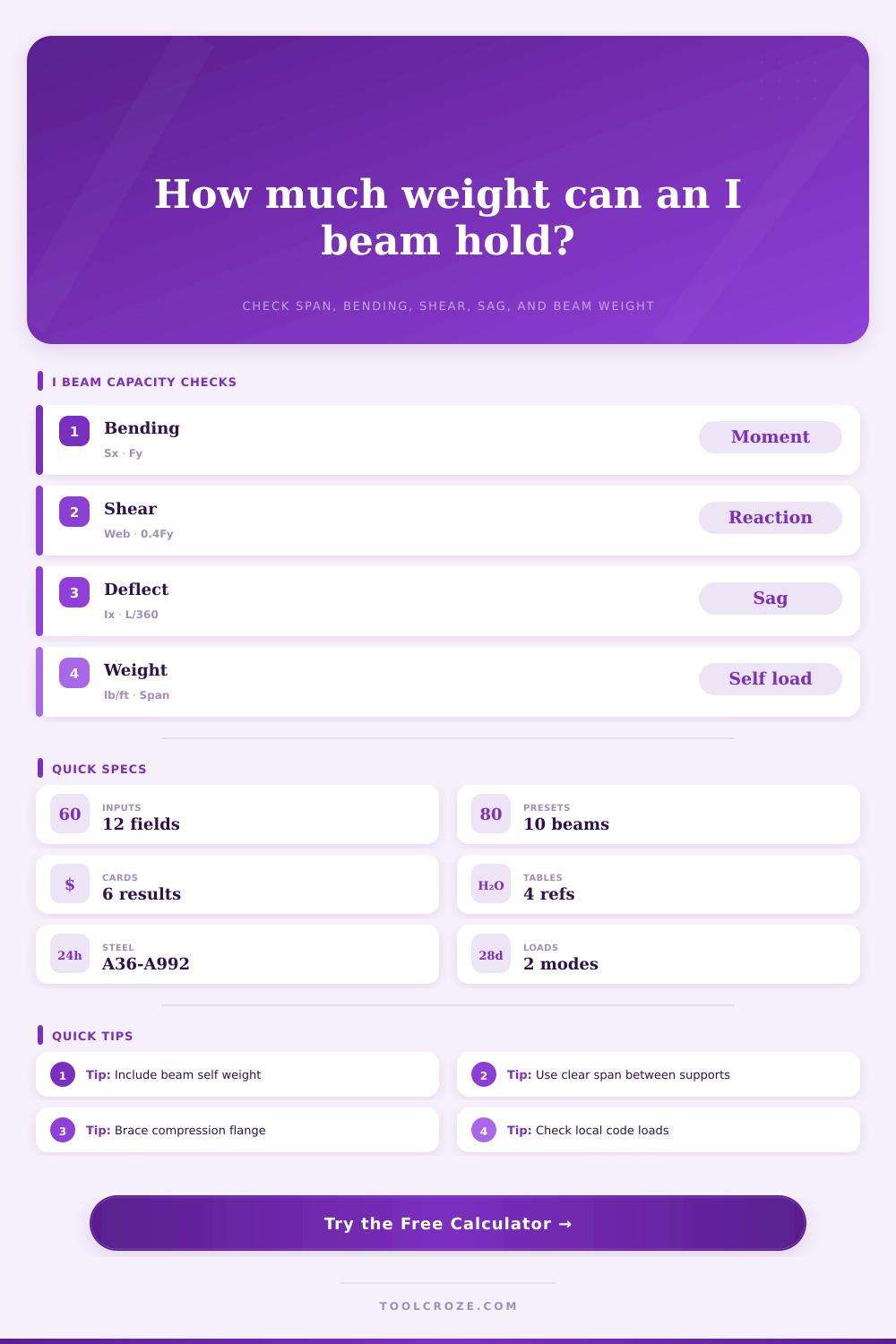
I Beam Weight Capacity Calculator
Estimate W and I beam capacity from span, section modulus, moment of inertia, support condition, steel grade, load pattern, self weight, bending, shear, and deflection limits.
I Beam Capacity Results
| Shape | Depth | Weight | Sx | Ix | Typical use |
|---|---|---|---|---|---|
| W4x13 | 4.16 in | 13 lb/ft | 5.46 in³ | 11.3 in⁴ | Short lintel |
| W6x15 | 5.99 in | 15 lb/ft | 9.72 in³ | 29.1 in⁴ | Small platform |
| W8x18 | 8.14 in | 18 lb/ft | 15.2 in³ | 61.9 in⁴ | Garage opening |
| W8x24 | 7.93 in | 24 lb/ft | 20.9 in³ | 82.8 in⁴ | Header beam |
| W10x22 | 10.2 in | 22 lb/ft | 23.2 in³ | 118 in⁴ | Floor beam |
| W10x30 | 10.5 in | 30 lb/ft | 32.4 in³ | 170 in⁴ | Column line |
| W12x26 | 12.2 in | 26 lb/ft | 33.4 in³ | 204 in⁴ | Longer span |
| W12x35 | 12.5 in | 35 lb/ft | 45.6 in³ | 285 in⁴ | Heavy bay |
| W14x38 | 14.1 in | 38 lb/ft | 54.6 in³ | 385 in⁴ | Shop frame |
| S8x18 | 8.0 in | 18.4 lb/ft | 15.1 in³ | 60.4 in⁴ | Standard I-beam |
| Support | Uniform moment | Point moment | Uniform deflection | Point deflection |
|---|---|---|---|---|
| Simple span | wL²/8 | PL/4 | 5wL⁴/384EI | PL³/48EI |
| Fixed ends | wL²/12 | PL/8 | wL⁴/384EI | PL³/192EI |
| Cantilever | wL²/2 | PL | wL⁴/8EI | PL³/3EI |
| Self weight | Included as w | Uniform load | Included in sag | Added to demand |
| Steel grade | Fy | Base bending | Base shear | Common note |
|---|---|---|---|---|
| A36 | 36 ksi | 0.66Fy | 0.40Fy | Older shapes |
| A572 Gr 50 | 50 ksi | 0.66Fy | 0.40Fy | Modern beams |
| A992 | 50 ksi | 0.66Fy | 0.40Fy | Common W shapes |
| A913 Gr 65 | 65 ksi | 0.66Fy | 0.40Fy | Special design |
| Limit | Typical use | 20 ft span | Controls what | Practical note |
|---|---|---|---|---|
| L/240 | Roof beams | 1.00 in | Total sag | Flexible |
| L/360 | Floor beams | 0.67 in | Comfort | Common check |
| L/480 | Brittle finish | 0.50 in | Cracking | Stiffer |
| L/600 | Equipment | 0.40 in | Alignment | Strict |
| L/720 | Very stiff work | 0.33 in | Vibration | Very strict |
When you imagine a steel beam failing, perhaps you imagine it snapping in half. That doesn’t actualy happen very often. In real world, a beam fails by giving up long before reaching its material strength. It sags, and keeps on sagging till the door frame jams shut, tile floor cracks or the drywall splits open. What you need to know is that when we talk about structural capacity, we’re not only talking about if steel can hold your weight without breaking. We’re talking about whether building will still be comfortabley to live in.
To use the calculator, simply enter your section properties and span and the calculator will do the rest. No need to remember equations for deflection and bending moment. Clicking isn’t nearly as important than knowing what to click.
How to Use the Steel Beam Calculator
What do we put into this thing? Well, first, separate out the weight of the beam from the load the beam has to support. A W12x35 steel beam alone weigh thirty-five pounds per foot. That’s a lot. When you consider over a twenty-foot span, we’re dealing with seven hundred pounds of dead load just sitting there. We have to account for that self weight, otherwise you’re designing a beam for a ghost. You can turn that feature on or off with the calculator. Leave it on almost all the time.
Steel grade selection isn’t as important as you think. With few exception, all wide flange shapes manufactured today has a yield strength of fifty thousand pounds per square inch (A992). Lighter sections or older shapes may be A36, which yields at thirty-six thousand. This is substantial but relevant mostly for when the actual beam are very slender and long. For shorter spans, deflection dictates the design. The beam is safely below its limit and nowhere near it’s maximum strength. However, the floor bounce, the ceiling cracks, and the beam is judged insufficient even though it would withstand loads without failure.
Moment of inertia, or Ix, is frequently more useful than section modulus, Sx. Ix quantifies resistance to bending deformation, while Sx quantifies resistance to stress. Both are needed but Ix gets the comfort vote. There are no physical limits to deflection. They’re all just social conventions. For floors, L over three hundred and sixty is typical (meaning the beam cannot sag more than the span divided by three hundred and sixty). It’s a social convention based off how much we can tolerate feeling things move, not any kind of law of nature. For a roof without any brittle finish material, L over two hundred and forty is okay. For something holding up a heavy machine, maybe L over seven hundred and twenty. You get to choose the criterion using the calculator. Choose well: A beam that satisfies strength but fails on deflection are still a failure, even though it passes on paper.
The silent killer of beam designs is lateral torsional buckling: the top portion of the beam (the compression flange) desires to buckle sideways with no one there to hold it in place. That’s where the unbraced length input comes into play. Say you’ve got a beam spanning 12-feet but only bracing it on both ends. Now what’s it got to lean against? Nothing. And so the beam twist and fails at a fraction of its theoretical capacity. By bracing the top flange at regular intervals, every six feet, for example, the beam can carries its full load again. This small construction detail change the whole capacity calculation.
For most floor beams shear is typically not an issue. Bending and deflection will control unless you’ve got some huge concentrated load directly on top of a support. The vertical plate in the center (the “web”) of the beam does pretty well with vertical loads. Shear will still get checked by the calculator, but it’s good practice anyway. Better to be surprised by a check than by a colapse.
Now lastly, know that this is an estimate. That’s what actualy happens in real structural engineering. Codes are followed. Connections are designed. Load combinations are considered. Safety factors is applied. You should of used the calculator more often.
This beam calculator helps you understand the span vs weight vs depth trade offs. Does a W10 work? Or do I really need a W12? How much can steel carry? What’s the starting point when talking with a pro? Steel is strong, but it isn’t magical. It obeys material science and geometry. Obey those laws and your beams will perform. Disregard the deflection and your walls won’t either.