Rebar Splice Length Calculator
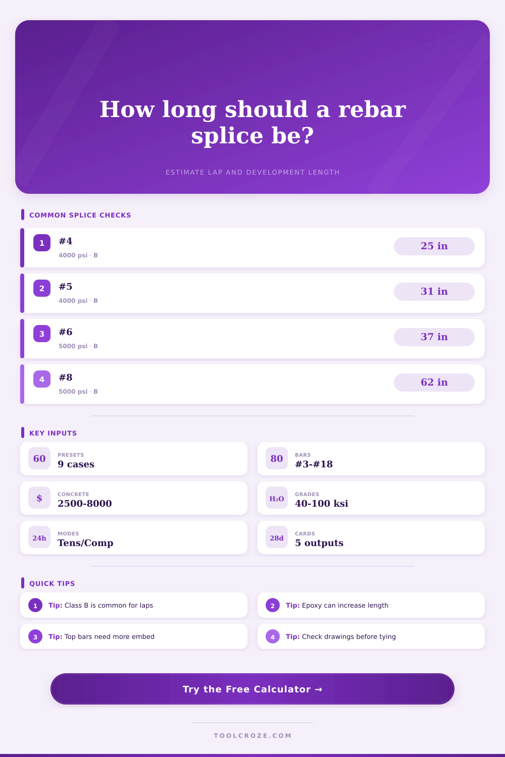
Estimate lap splice and straight development length using bar size, concrete strength, steel grade, coating, top-bar placement, confinement, lap class, and tension or compression mode.
The calculator uses common ACI-style development length relationships for quick detailing estimates. Final splice lengths must follow the governing code, project drawings, bar layout, cover, spacing, and engineer-of-record requirements.
Splice length estimate
US rebar size data
| Bar | Diameter | Area | Typical use |
|---|---|---|---|
| #3 | 0.375 in | 0.11 in² | Stirrups, small slabs, light mats |
| #4 | 0.500 in | 0.20 in² | Slabs, walls, patios, light footings |
| #5 | 0.625 in | 0.31 in² | Walls, grade beams, footings |
| #6 | 0.750 in | 0.44 in² | Beams, mats, retaining walls |
| #8 | 1.000 in | 0.79 in² | Columns, heavy beams, foundations |
| #11 | 1.410 in | 1.56 in² | Large mats and heavy structural members |
Factor guide used by this calculator
| Condition | Factor | Effect | When to use |
|---|---|---|---|
| Top bar | 1.30 | Longer tension length | More than 12 in fresh concrete below bar |
| Epoxy, good cover | 1.20 | Longer bond length | Coated bars with favorable spacing |
| Epoxy, tight cover | 1.50 | Longest coating case | Tight cover or close spacing |
| Class B lap | 1.30 | Common lap multiplier | Most tension splice detailing |
| Lightweight | 0.75-0.85 | Longer length | Reduced concrete bond factor |
| Good confinement | 0.85-0.90 | Shorter estimate | Generous cover, spacing, or ties |
Lap class and minimum checks
| Mode | Multiplier | Minimum | Detailing note |
|---|---|---|---|
| Tension development | 1.00 x Ld | 12 in typical screen | Anchorage length, not a lap by itself |
| Class A tension lap | 1.00 x Ld | 12 in typical screen | Only when code conditions are satisfied |
| Class B tension lap | 1.30 x Ld | 12 in typical screen | Common default for tension lap splices |
| Compression splice | Compression rule | 12 in typical screen | Check larger bar when sizes differ |
Common detailing examples
| Scenario | Bar | Concrete | Starting class |
|---|---|---|---|
| Slab-on-grade mat | #4 | 3000-4000 psi | Class B tension lap |
| Basement wall vertical | #5 | 4000 psi | Class B tension lap |
| Beam top reinforcement | #6 | 5000 psi | Class B with top-bar factor |
| Column vertical bars | #8 | 5000 psi | Compression splice check |
| Bridge deck coated bars | #5 | 4500 psi | Epoxy tension lap |
| Foundation mat bars | #11 | 6000 psi | Class B or mechanical splice |
You might notice something that causes panic: there is no way for the rebar cage to extend out to where the footings are on each side. If it’s too short (or your layout changed) then two have to overlap so they can shares the load. Butt’em up against each other? Nope. You gotta give concrete some length to wrap around steel, and the whole thing has got to hold together as it stretches. That’s what splice length is all about.
Code minima isn’t the only consideration. There’s some physics going on here. How is the steel supposed to get bonded with cement paste? It happens through the use of space. After you set your parameters, the calculator do the math. It’s based off things like concrete strength, bar diameter, and coating type, and it calculates how much overlap are necessary. What matters here is that you know WHY the inputs change the output… So you don’t end up overspending on something you could of done yourself.
How to Calculate Rebar Splice Length
Let’s begin with bar size. The bigger the bar, the greater its surface area, but it also resist more. This isn’t a straight-line relationship. Doubling the bar size doesn’t double the length, right? That’d be too easy. Bond stress distribute differently depending on the shape. This isn’t a one-size-fits-all solution. To account for this, the tool factors in the bar diameter directly so you won’t under-estimate the grip provided by a big ol’ #11 compared to skinny little #4. A tighter bond = stronger concrete.
The stronger the material (e.g., if you’re using a 4,000 psi mix rather than 3,000 psi), the shorter the splice need to be. It is a straightforward tradeoff. Then again, we add some complexity with the placement conditions. Water and air will rise up through fresh concrete, forming a layer of laitance under the bar which weaken its bond. To compensate, the calculator increases required length for top bars, typicaly by thirty percent. It is a small multiplier, but a real physical gap in adhesion that leads to cracks where there shouldn’t be.
Then there’s a coating. In bridges or on marine applications, it’s common to have epoxy coated bars. These prevent corrosion but also make the surface slick so the concrete has less grip. So you’d want longer bars to make up for lower friction.
Spacing is critical. The tool tells you which cover is too thin and which cover is good; when bars are crowded together too much, the concrete doesn’t fully wrap around them, resulting in a weaker bond. If you don’t adjust detailing based on having a protective layer, that protection can become a structural risk.
Finally, the outcome depends on the class of the splice. There’s a class A splice and there’s a class B splice. Class A has strict conditions on concrete cover and spacing requirements that is difficult to achieve in the field. So engineers generally want to go with class B unless you have good reason (and then they call it out explicitly). Most engineers like to be conservative so class B are their typical selection on site. The calculator defaults to Class B.
Don’t take it for gospel though. It’s a guess based upon typical assumptions. Theory is messed up in the real world. Debris on the mat, poor curing, or vibration when poured can all weakens the bond. Always look at the structural drawings. Sometimes they call out mechanical splices or even welded connections because there just isn’t enough room for a lap. Use the math as a starting point, get the truth from the site.
Detailing rebar is a dance between verifying and trusting. The code tells you to do it this way… So you verify by making sure it fits. If you have the correct splice length, then the structure will work as designed. There will be no weak points and no waste. This is the difference between a good joint and a bad one. Measure twice, calculate once, and pour with confidence.