Rebar Size Calculator
Choose a reinforcing bar by required steel area, target spacing, slab, wall or beam mode, clear cover, bar diameter, unit weight and development length checks.
This calculator sizes bars from required steel area and spacing. It is a planning tool; final reinforcement must follow the engineer's drawings, local code and project specifications.
Calculation Breakdown
| Bar size | Nominal diameter | Area | Weight per foot | Typical use |
|---|---|---|---|---|
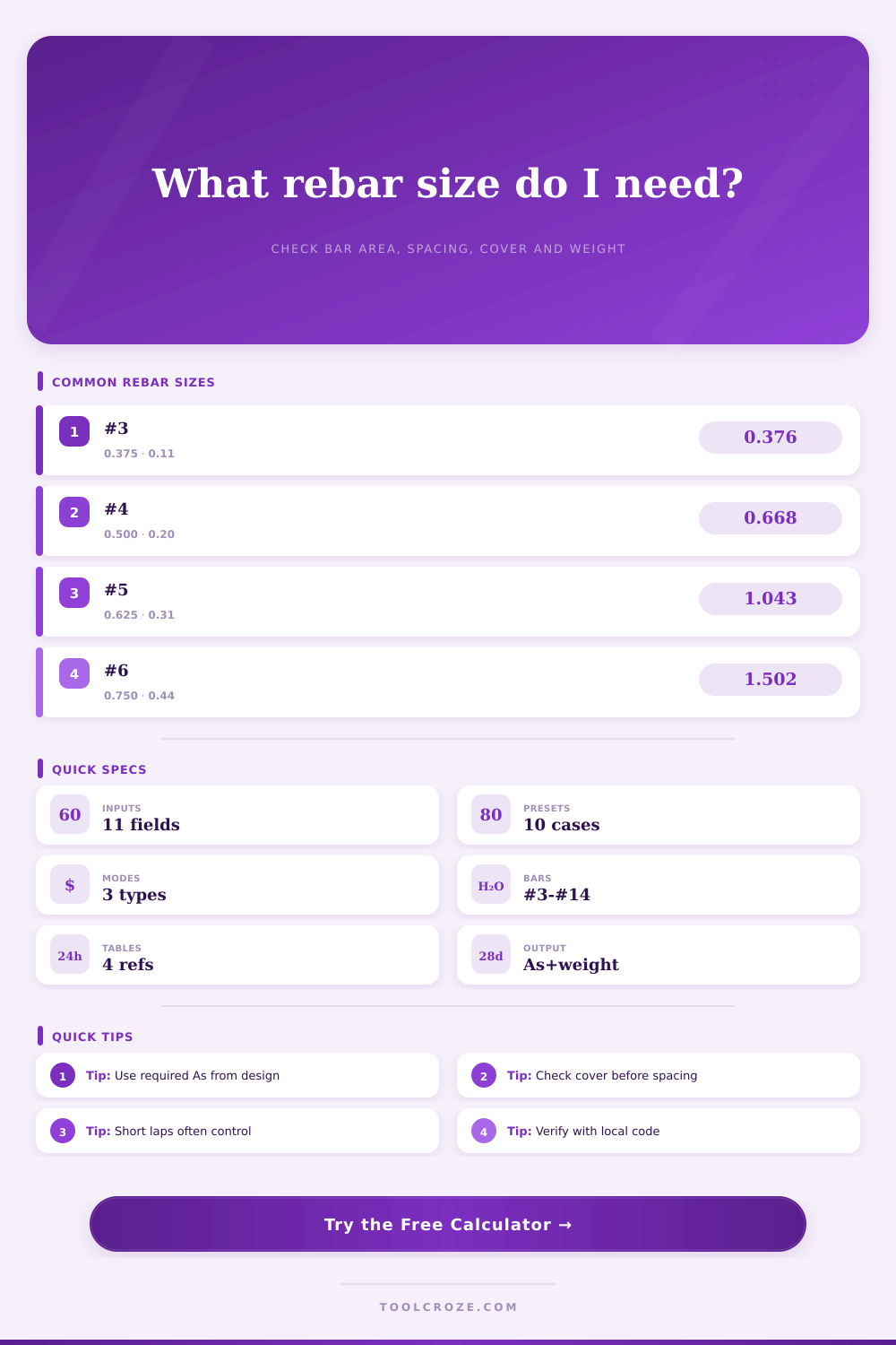
| #3 | 0.375 in | 0.11 in² | 0.376 lb/ft | Light slabs, ties, small walls |
| #4 | 0.500 in | 0.20 in² | 0.668 lb/ft | Residential slabs, drives, small footings |
| #5 | 0.625 in | 0.31 in² | 1.043 lb/ft | Footings, walls, heavier mats |
| #6 | 0.750 in | 0.44 in² | 1.502 lb/ft | Grade beams, retaining walls, columns |
| #7 | 0.875 in | 0.60 in² | 2.044 lb/ft | Structural beams and heavily loaded walls |
| #8 | 1.000 in | 0.79 in² | 2.670 lb/ft | Beams, piers and deep foundations |
| #9 | 1.128 in | 1.00 in² | 3.400 lb/ft | Heavy beams and mat foundations |
| #10 | 1.270 in | 1.27 in² | 4.303 lb/ft | Major foundation and transfer members |
| #11 | 1.410 in | 1.56 in² | 5.313 lb/ft | Large concrete beams and columns |
| #14 | 1.693 in | 2.25 in² | 7.650 lb/ft | Heavy structural reinforcement |
| Bar size | 6 in spacing | 8 in spacing | 12 in spacing | 18 in spacing |
|---|---|---|---|---|
| #3 | 0.22 in²/ft | 0.17 in²/ft | 0.11 in²/ft | 0.07 in²/ft |
| #4 | 0.40 in²/ft | 0.30 in²/ft | 0.20 in²/ft | 0.13 in²/ft |
| #5 | 0.62 in²/ft | 0.47 in²/ft | 0.31 in²/ft | 0.21 in²/ft |
| #6 | 0.88 in²/ft | 0.66 in²/ft | 0.44 in²/ft | 0.29 in²/ft |
| #7 | 1.20 in²/ft | 0.90 in²/ft | 0.60 in²/ft | 0.40 in²/ft |
| #8 | 1.58 in²/ft | 1.19 in²/ft | 0.79 in²/ft | 0.53 in²/ft |
| Bar size | Rule of thumb lap | Min clear spacing | Cover check | Note |
|---|---|---|---|---|
| #3 | 18 to 24 in | 1.0 in | 1.5 in common | Often governed by constructability |
| #4 | 24 to 32 in | 1.0 in | 1.5 to 2 in | Common residential slab bar |
| #5 | 30 to 40 in | 1.0 in | 2 in common | Good for walls and footings |
| #6 | 36 to 48 in | 1.0 in | 2 to 3 in | Check bend and hook detailing |
| #7 | 42 to 56 in | 1.0 in | 2 to 3 in | Usually structural detailing |
| #8 | 48 to 64 in | 1.0 in | 2 to 3 in | Development can drive layout |
| Mode | Steel area basis | Spacing basis | Quantity basis | Best use |
|---|---|---|---|---|
| Slab | in²/ft strip | Bars across slab width | Parallel bars by run length | Slabs, mats, pavement panels |
| Wall | in²/ft height or length | Vertical or horizontal grid | One face or two faces | Basement and retaining walls |
| Beam | Total in² in member | Bars fitted across width | Continuous longitudinal bars | Beams, lintels, strip footings |
| Metric | mm²/m or total mm² | mm center spacing | Converted internally | Same logic with metric entries |
For most folks, “pouring concrete” is synonymous with “dumping gray slurry in a hole and waiting.” The truth is, the hidden steel within it, called rebar, is what makes it strong. That is where how you place it and ratio you use affect the strength of your structure. Properly reinforcing it require accounting for how much steel is needed without making the rebar too close to limit practicality. In other words, tying together real-world bars on a busy jobsite translate these engineering numbers into something tangible.
Enter the calculator above: It’ll do the math for you so that those area needs becomes actual bar sizes and spacing intervals. Knowing what they mean ahead of time avoids an expensive error when the concrete truck pulls up. In short, basic idea is feet of width divided by square inches of steel used (sometimes called As on design drawings). It doesn’t take an engineer’s degree to understand how important it is, but it takes enough of one to respect it.
How to Plan Rebar for Concrete Projects
Say the drawing specifies a certin amount of steel area required per linear foot. That means either using a few big bars spread way apart or a bunch of little ones packed closely together would work. Each with its own tradeoff. The former is simple to handle separately, but difficult to force into tight spaces between member where other restrictions prevent closer spacing. The latter bends easily because it’s so thin and flexible. However, tying something that small that closely together is time-consumng drudgery, which will slow your crew.
Clear cover is the distance from the outside of the concrete to the first piece of embedded steel. While it sounds like a nice-to-have, it’s actually required for corrosion control purposes. Oxygen and moisture is kept away from the steel by the concrete. When the cover is insufficient, the water makes its way to the bar and causes rusting. This rusting cause expansion and cracks in the surrounding concrete (from the inside). To make sure there is good concrete placement around the steel, various rebar sizes has varying minimum cover requirements. In general, the bigger the diameter then more cover needed. That being said, don’t just cram the rebar into your form work and expect things will be okay. Good cover will extend life of the steel to the same time as building it holds up.
Another useful feature is ability to estimate weights. This is important because it lets you know how many feet of steel to buy without dumping more in than can be stored or having truck run out mid-pour. The tool estimates total weight of the job by using number and length of the bars plus an assumed waste factor. A good rule of thumb would of ten or fifteen percent waste. There are always offcuts from cutting, bending and lap splicing. Don’t forget that waste allowance, or you’ll find yourself making a last minute trip to the supplier hours before the pour. Better to have some spare footage of your bar than to try to patch things together after the pour with an incompatable epoxy.
Special mention goes to rebar development length and lap splices: The moment diagram doesn’t precisely indicate where steel begins and ends. To transfer force through bond stress, some amount of steel must be embedded in concrete. That’s the development length. For continuity, two bars meeting each other must overlap one another for a specified distance called the lap length. The larger the bar, the greater the required lap length. At times, a number eight may have almost five feet of lap, while a number four has much less. This eats up floor space and can also clog up reinforcement cages in cramped spaces such as beam-column joints. If checked early, you can plan your bar lengths so that few splices occurs in high-stress regions.
All in all, what we are doing here is detailing rebar with intention. And though the calculator gives you starting points for weight, size, and spacing, details of your site determine how things will end up laid out. Concrete doesn’t forgive sloppy prep. Splice too short? Bar touching the formwork? You can’t do anything once it’s set. Make sure you double check the inputs against real world measurements of members and any local code demands. Do this right, and a few well placed bars work for decades without a sound. They quietly support everything while the concrete supports the load. It’s good to plan for something so reliabel (and quiet).