Rebar Calculator for Wall
Estimate wall rebar quantities by spacing, bar size, curtains, lap length, openings, cover, stock length, waste, and reinforcement ratio.
⚙Unit System
🏗Wall Presets
📏Wall Layout Inputs
Wall Rebar Estimate
Calculation Breakdown
🧱Material and Specification Grid
📊Bar Size Reference
| Bar size | Diameter | Area | Weight |
|---|---|---|---|
| #3 / 10M | 0.375 in / 9.5 mm | 0.11 in² | 0.376 lb/ft |
| #4 / 13M | 0.500 in / 12.7 mm | 0.20 in² | 0.668 lb/ft |
| #5 / 16M | 0.625 in / 15.9 mm | 0.31 in² | 1.043 lb/ft |
| #6 / 19M | 0.750 in / 19.1 mm | 0.44 in² | 1.502 lb/ft |
| #7 / 22M | 0.875 in / 22.2 mm | 0.60 in² | 2.044 lb/ft |
| #8 / 25M | 1.000 in / 25.4 mm | 0.79 in² | 2.670 lb/ft |
📐Wall Spacing Reference
| Wall condition | Vertical spacing | Horizontal spacing | Typical curtain |
|---|---|---|---|
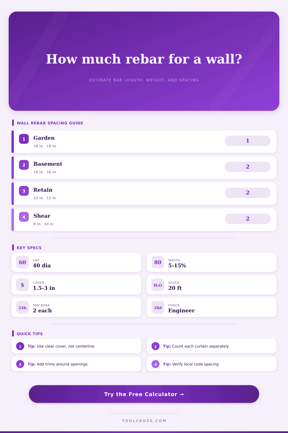
| Short garden stem wall | 18 to 24 in | 18 to 24 in | Single |
| Basement wall | 12 to 18 in | 12 to 18 in | Double |
| Retaining wall | 8 to 16 in | 10 to 16 in | Double |
| Shear wall | 6 to 12 in | 6 to 12 in | Double |
🔗Lap and Cover Reference
| Detail | Common value | Use in calculator | Field note |
|---|---|---|---|
| Lap splice | 40 bar diameters | Lap input | Engineer may require more |
| Interior formed cover | 1.5 to 2 in | Cover input | Keep chairs consistent |
| Earth side cover | 2 to 3 in | Cover input | Do not reduce at corners |
| Openings trim | 2 bars around | Openings area | Add jamb and sill bars |
🗂Common Wall Preset Reference
| Preset | Wall size | Bar pattern | Allowance |
|---|---|---|---|
| Garden Stem Wall | 20 ft × 3 ft | #4 at 18 in | 5% waste |
| Basement Wall 8 ft | 32 ft × 8 ft | #4 at 16 in | 10% waste |
| Retaining Wall 10 ft | 40 ft × 10 ft | #5 at 12 in | 12% extra |
| Seismic Boundary Wall | 28 ft × 12 ft | #5 at 8 in | 20% total |
💡Rebar Layout Tips
Calculated reinforcement ratios are approximate gross steel ratios for screening. They are not a substitute for structural design.
Standing in the void of your former back yard, you look down at two identical shapes filled with soggy gray goo. A team of concrete guys is waiting for your go-ahead, and you know that sticking rebar blindly will create cracks in your basement walls, and extra expense. It’s not just about tossing some rods on top of the concrete mix. Before truck rolls up, there is a lot of math to consider: Spacing, tension, laps, waste, etc. Do this wrong, and you’ll have extra steel you can’t send back to the yard; do it right, and you’ll save money and keep things tight.
Plug in your wall dimensions and bar choices into the calculator above and let it do the math. No more manually dividing and then making mistakes by dividing again with a decimal point in the wrong place. Begin with the physical envelope: what are the dimensions of the wall? Enter its length and height, excluding large openings like doors or windows.
How to Use the Rebar Calculator
The next step is the clear cover. That’s how far out from the outside face of the concrete the steel sits. An inch and a half inside is fine on an indoor wall, but three inches on exterior walls facing soil so there’s no rust issue. Moisture will penetrate the concrete and never bond well with the steel if placed to near the formwork. This is another small detail, but it are important for longevity.
Now examine your grid’s density. How well will it resist lateral forces from wind or soil? Generally speaking, the closer together the bars is in each direction (vertically and horizontally), the stronger the wall. An eighteen-inch separation might work for a simple garden stem wall, but a retaining wall holding back a hillside call for tighter grids of twelve inches or less.
With this tool, you choose varying bar sizes in both directions. In the real world, one axis often carries more load than another; here, too, you don’t have to assume all bars is equally sized. You can mix their sizes to save weight without losing strength, as long as you keep the spacing consistent.
Estimates fail at the joints. By default, standard stock bars will be supplied in twenty foot lengths. So if your wall is eight feet tall, it seems like one piece should of been fine, right? But what if there’s a long horizontal run or several lifts requiring continuity? The calculator includes lap splices based off bar diameter. A common rule of thumb is to provide forty diameters of overlap for deformed bars. That’s two feet of overlap on a number four bar, adding considerable length to your overall requirement. It is easy to see how people miss the mark by estimating net length rather than developed length and end up with bars too short to span from one end to another, leaving field cutting and improvised work.
One big cost consideration is waste. When you cut steel, you create scrap. Cut-off corners and bar ends bent into openings create unusable pieces of metal. Ten to fifteen percent waste allowance is realistic, not over conservative. There’s a field on the tool for this. If your walls has lots of little windows or intricate detail, nudge it up there.
Boundary bars are installed at each end of the wall, too. These focused pieces bear the brunt of stress concentrations which distributed grid steel can’t handle by itself. These is a must in seismic areas and are good anywhere.
How much does it weigh? How many tons of steel do I need? How big of a truck will it require? How many people will be required to move it into place? The weight tables gives an easy reference point so you know if you are looking at 2 tons of steel or 500 pounds of steel. That changes how much truck you will need and what kind of equipment you bring to get it there. You also know from the table if the bar weight and density make sense. A number eight bar is more than twice as heavy than a number four bar per foot. If your wall is high that weight add up quickly.
In the end though, that’s what this exercise comes down to: visualization followed by implementation. It’s laying out the skeleton of the thing. Give it to your supplier with confidence when the numbers seem to add up and the ratios make sense. Don’t aim for perfect estimates; aim to eliminate any surprises on site. A good plan fits the bars where they go, aligns the laps where they need to be, and lets the concrete flow around them without getting trapped and holding air. That’s how you create a solid foundation from a hole in the ground.