
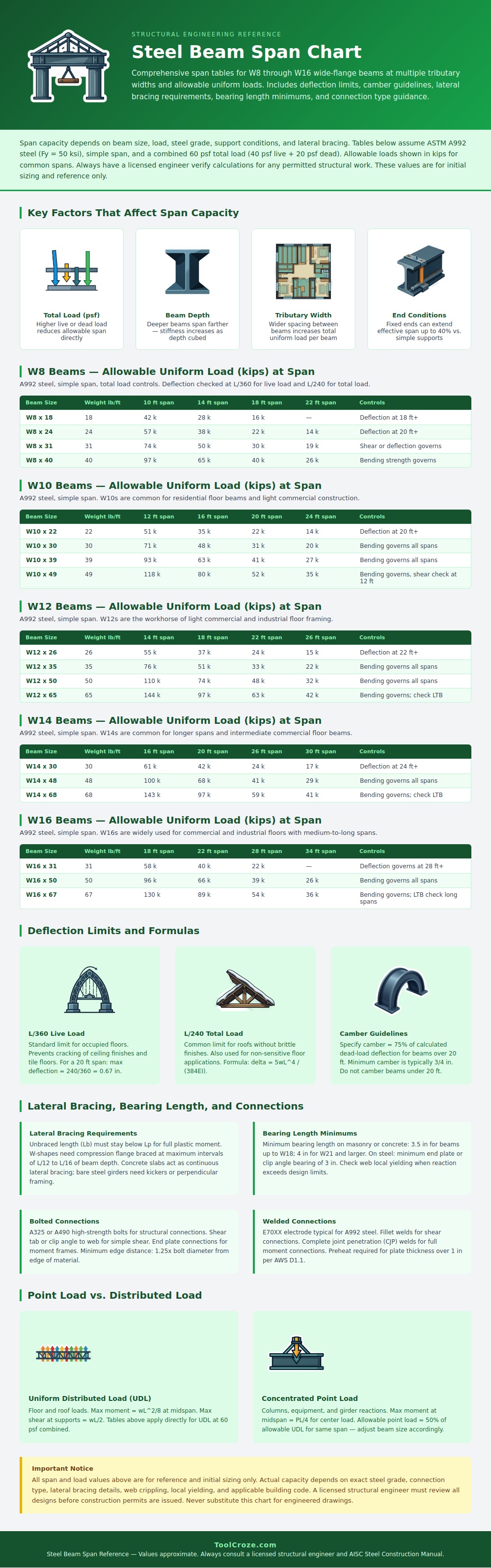
If you’re looking for a ballpark figure for your material requirements without thinking like an engineer, here’s the beginning of a table I made (above). It is for sizing wide-flange beams ranging in size from W8-W16. This assumes a default load combination of 60 pounds per square foot, typical ASTM A992 steel, and most home interiors furnished at a moderate density.
These are just guideposts; don’t oversize or undersize based off them, since there’s a huge range of price difference between swapping out one beam versus retrofitting the whole foundation.
How to Use This Beam Size Guide
In terms of stiffness, beam depth is more significant then its weight. Stiffness increase by cube of depth, so a deep beam resist bending much better than a wide, heavy, shallow one. For example, a W8 is fine in short spans (and even quite light) but struggle in longer span. That’s why we frequently use W12 and W14 beams in light commercial framing.
And as the table indicates, as span length increases, allowable loads goes down because beam deflects too much, not necessarily that it fails in any way. It just might be bouncy underfoot, or sag enough to crack your drywall… Which although technicaly still safe, is a performance issue. There is also one more important limiting condition: deflection. Building code require that L/360 deflections apply to all live loads, including those on occupied floors. That’s both a comfort and finish issue. You don’t want a 20′ span to flex as little as three-quarters of an inch under foot traffic, otherwise while the floor itself may be fine, the ceiling below will crack into a mess of spiderwebs. Deflection checks goes with strength in the reference guide so you know what will rule your design at every span.
Steel beams also have a tendency to buckle out-of-plane (lateral) when compressed like a soda can beneath someone’s foot, and that’s why lateral bracing is so important. In the chart, I’m assuming steel beam has been properly braced through perpendicular framing members or concrete slabs which are tied into the flange. A free standing girder will perform several times worse then what the table suggests, regardless of the steel size. The actual performance in real life are dictated by boundary conditions.
Connection details also dictate performance in ways that feel counterintuitive until you see them fail. For instance, there is strict limits on minimum bearing length on masonry and concrete to prevent local yielding. For smaller beams, this is typically three and a half inches of bearing length. For instance, there are strict limits on minimum bearing length on masonry and concrete so that it doesn’t yield locally, typicaly three and a half inches of bearing length for smaller beams. There are detailed limits on size of welds and edge distance for welded end plates and bolted shear tabs that adequately transmit force. Poor detailing of connections can result in a good beam sliding out from under itself during a heavy load or earthquake event, making the beam useless at that point.
You should of known this. Remember: These tables are for preliminary planning purposes; they do not represent final construction documents. Professionals need to review local code amendments, column point loads, and other conditions specific to each project’s site.
Don’t try to shortcut process with this knowledge. Instead, use it to talk more effectively with your structural engineer. Early decisions about span saves money down the road, and transform fuzzy concerns into a concrete plan you can count on.
