
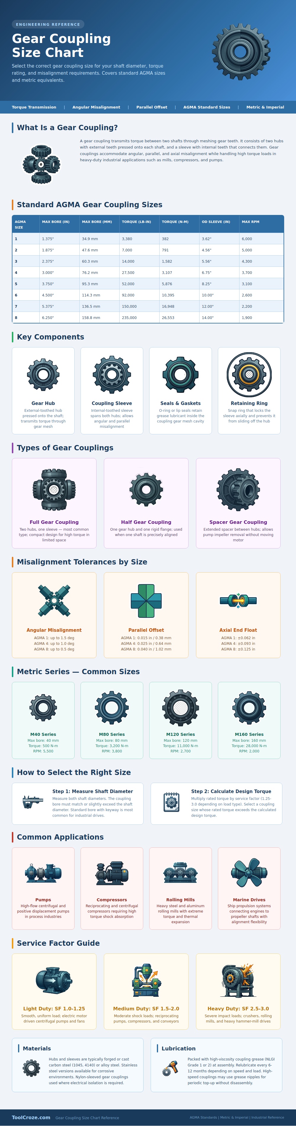
If you’ve ever had one of those moments where a critical machine failure occurs because you install a new coupling and it doesn’t fit, it’s likely because someone doesn’t understand the interaction between alignment, shaft size, and torque required to operate heavy machines effectivly. That’s why we broke it down into standard AGMA sizes in the chart above: Each torque rating is matched with exact bore dimensions. Get the specs right and you’re looking at a smooth startup; get them wrong and you’re talking about a catastrophic failure and shut down of your whole line for days waiting on a custom part.
A gear coupling is really just a matter of teeth meshing. A sleeve with internal teeth fits between two hub with external teeth, and these teeth press firmly against their shafts. It can handles huge amounts of torque load in pumps, compressors and mills, and it also accounts for parallel and angular misalignment. How does it do this? There is a bit of room to move around in that grease-filled tooth cavity. There is no loss of power transmission. However, there is enough give to account for any small changes in shaft position caused by thermal expansion during operation. That is where the flexibility comes in.
How to Choose the Right Gear Coupling
First step is to measure your shaft diameter precisely. Bore sizes vary widely, from tiny one-inch bores up to huge six-inch and larger openings. To engage the key way properly, you want the bore of the coupling to be at least as large as or a little bigger than your shaft diameter. Most industrial drives uses standard bores (with keyways) because this ensures consistent torque transfer without slippage.
Finally, you multiply your rated torque by a service factor for your design torque. This is where most folks go wrong. They purchase a coupling that’s barely adequate for the nominal rating while neglecting any vibration or shock load their particular application will encounter. Those are described clearly in the infographic. A light duty centrifugal fan may only require a factor of one point two five, whereas something like a rolling mill or crusher demands a factor as high as three. Neglecting the factor means unexpected downtime and accelerated wear.
Then there’s material selection. To be strong, most couplings consist off an alloy or carbon steel hub and sleeve. For corrosive applications, they’re available in stainless steel. And some systems also use nylon-sleeved couplings to electrically isolate the motor from the driven device, avoiding ground loops which can ruin sensitive electronics. It is a little thing but it is huge in today’s automated plant.
You also can’t ignore maintenance with these things. At installation they must have thick grease applied, but they need periodic relube every six months to a year thereafter. That lube stays where it should… In the gear mesh cavity because of retaining rings and seals. Failure of these seal allows contamination to get into the mix and accelerates wear on those valuable involute teeth. Save yourself some money down the road by checking your grease fittings as part of your normal maintenance.
The bottom line: Choosing the right size gear coupling isn’t as much a matter of memorization as it is of knowing what your system requires. Reference the chart above; identify the required torque (or if known, the bore), and assign the proper service factor based on your load type. If you honor these parameters, your machinery will last longer, operate quieter and maintain your production schedule. That first bout of panic would of never happens.
