Truss Bridge Calculator
Estimate bridge span geometry, panel loads, reactions, chord force, web force, service deflection, and member utilization for preliminary truss bridge planning.
⚙Bridge Presets
📏Bridge Inputs
Bridge Calculation Results
🧱Material and Spec Grid
📊Reference Tables
| Truss Type | Good For | Depth Start | Force Behavior |
|---|---|---|---|
| Warren | Light pedestrian and short service bridges | L/7 to L/9 | Alternating diagonal tension and compression |
| Pratt | Footbridges and steel spans with tension diagonals | L/6 to L/8 | Diagonals usually tension under gravity load |
| Howe | Timber bridges with compression diagonals | L/6 to L/8 | Verticals often tension, diagonals compression |
| K Truss | Longer concept spans with shorter compression webs | L/7 to L/10 | Splits web forces into shorter members |
| Bowstring | Walkways where arch action reduces chord force | L/8 to L/12 | Curved top chord carries compression thrust |
| Bailey Panel | Modular temporary or portable service bridges | Panel depth fixed | Demand depends strongly on panel stacking |
| Material | Elastic Modulus | Planning Stress | Density |
|---|---|---|---|
| Structural steel tube | 29,000 ksi | 21.6 ksi | 490 lb/ft³ |
| Weathering steel | 29,000 ksi | 30.0 ksi | 490 lb/ft³ |
| Aluminum box section | 10,000 ksi | 18.0 ksi | 169 lb/ft³ |
| Glulam timber | 1,800 ksi | 1.6 ksi | 35 lb/ft³ |
| Treated sawn timber | 1,400 ksi | 1.1 ksi | 40 lb/ft³ |
| Pultruded FRP | 3,000 ksi | 10.0 ksi | 115 lb/ft³ |
| Bridge Use | Common Width | Live Load Start | Deflection Check |
|---|---|---|---|
| Garden footbridge | 3 to 4 ft | 60 psf | L/240 to L/360 |
| Public pedestrian bridge | 5 to 10 ft | 90 psf | L/360 typical |
| Crowd assembly walkway | 8 ft plus | 100 to 125 psf | L/360 or stricter |
| ATV or mower crossing | 5 to 7 ft | 120 to 160 psf | Vehicle point loads also needed |
| Farm service span | 8 to 12 ft | 150 psf plus axle loads | Engineer vehicle load paths |
| Member Item | What To Check | Calculator Uses | Design Note |
|---|---|---|---|
| Top chord | Compression and buckling | Chord force divided by area | Unbraced length may control capacity |
| Bottom chord | Tension and splice strength | Same chord force envelope | Splices should align with panel forces |
| Diagonals | Axial tension or compression | Shear divided by sine of web angle | Compression diagonals need slenderness checks |
| Verticals | Panel point transfer | Panel load and web factor | Hang deck loads at intended panel points |
| Gussets | Bearing, tear-out, and block shear | Demand allowance multiplier | Connection design is usually decisive |
| Lateral bracing | Wind and top chord stability | Side load reaction estimate | Use X bracing or rigid portal frames |
💡Calculation Tips
Now imagine walking out onto a wooden bridge over a creek. You feel that slight bounce as you step down onto it. It is not frightening at all just enough to remind you this thing was built to hold up your weight against the force of gravity.
When most of us cross a bridge we don’t think much about what’s inside it, but the hidden skeleton are doing all the work, while the deck simply appears pretty. The truss system transfers gravity’s vertical pull into axial forces along triangles, naturaly rigid shapes. So instead of bending like a loose board, the steel or wood is pushing and pulling in straight lines. That’s why we can use less material to span greater distances then if we used a solid beam.
Understanding How Bridges Work
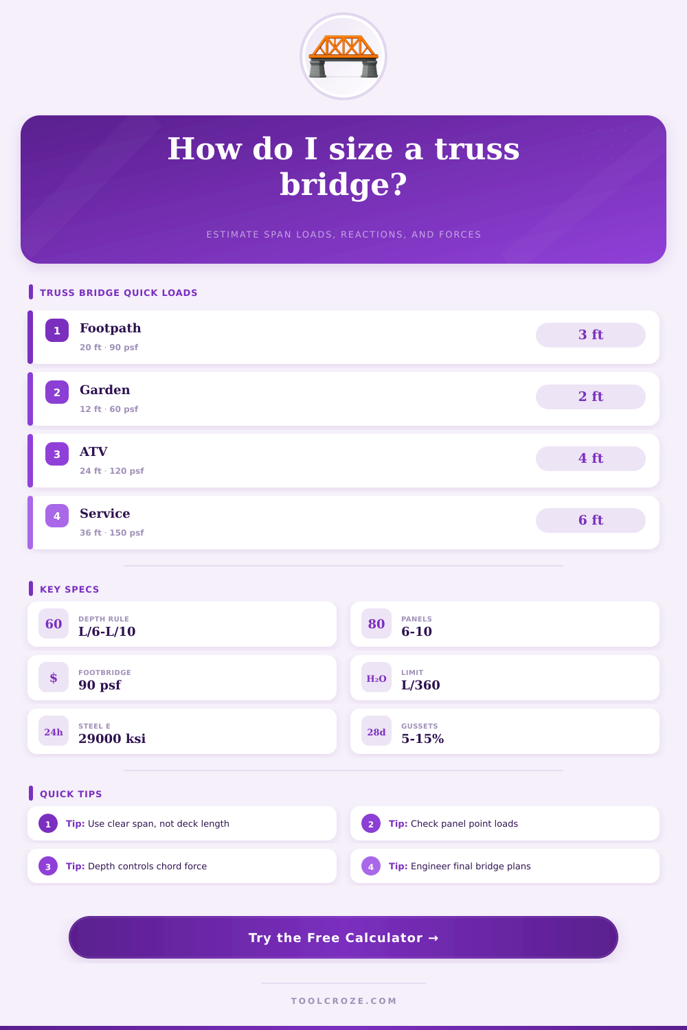
Whether it’s a farm service crossing or just a little footpath across your garden, once you decide how high off the ground you want your bridge to be (the “depth” of its truss), all the other details fall into place. The deeper the truss, the more leverage it have, and this means much less force is needed in the bottom and top chords to fight against being bent. This is one of those tradeoffs: more material volume vs more vertical clearance.
So if you’re limited on how far up you can raise your bridge; maybe because of low tree limbs overhead or power line crossings… Then you’ll need thicker chord members to offset the lack of depth. The calculator above lets you play with these relationships so you can get a better idea of what they look like. Need to know if a four-foot deep truss will hold up under a twenty-four foot span? Run the numbers! It happens instanty.
Geometry aside, the weight being carried also comes into play. For example, a pedestrian bridge built for light foot traffic is very different from one made to support farm machinery or ATVs. Static weights on pedestrian bridges tend to be around 90 pounds per square foot. Vehicles adds dynamic impact forces which increase these static weights. Add in the dead load of the decking material itself.
Wood is lighter than steel, but it’s not infinitely strong in compression without bracing. Using glulam timber helps because it has a higher strength-to-weight ratio; however, it does have a stiffness lower than steel, meaning it will deflect further under same load. This is not necessarily a point of failure, but it is something that affects long-term fatigue and user comfort.
Another way that many DIY builders trip themselves up is with the idea of panel point loading. A truss is designed to resist loads at the joint locations; NOT down the center of the chord members that connect the joints. When you place your structural supports halfway between panel points (i.e., when your deck beams land in the middle of the chord members), you create local bending moment in the top chord which isn’t realy captured by the simple axial force calculations that we did earlier.
That’s why the reference tables in the tool give you some recommended numbers of panels for each span length. By lining up your structure supports with the nodes of the truss, you know that the load travels straight through the compression and tension members as intended. It’s a little thing but makes all the difference in the structural efficiency of the design.
The material really makes all the difference. Long-span structures can use steel with little deflection due to its high stiffness of roughly twenty-nine thousand ksi. Aluminum is lighter and resists corrosion well; however, it deflects much more readily, necessitating extra bracing or stiffer members to achieve serviceability limits. For those seeking tradition and warmth (or covered bridges) timber are an option, though it requires thoughtful connection design.
Bolts and gusset plates needs to move force from one member to another without tearing through wood fibers. Joint failures is not uncommon if member sizes appear adequate on paper but lack proper anchorage. These joints require allowances in the tool.
Always plan for some kind of safety factor when doing initial estimates. Two is reasonable to start with, but that’s for non-critical structures where minor flaws in materials or extra loading won’t cause issues. Bridges, on the other hand, are life-safety items. What is adequate for backyard use may not withstand public inspection or dynamic environmental changes (think wind and flooding).
Deflection limits, like L/360 for serviceability in the references here, are there to ensure people aren’t jostled too much. You’ll probably want to increase depth or number of panels if yours comes out over that limit, not simply thicken the members.
To sum it up though, a truss bridge is forces acting together to make something beautiful. It’s more than stacking steel or wood; it’s guiding compression and tension in exact directions. Get that first size roughly right by using the tool, pay close attention to panel alignment, and always double-check your final design against an experienced engineer.
If there’s that slight give underfoot, let it give you confidence, not worry. You should of checked with someone first.