
If you’ve ever cut aluminum on a lathe, then you’re familiar with chatter, but even if you increase feed rate or throw some coolant on the chuck, you still can’t rid yourself of this aggravation. It is rarely the lathe. More likely than not, it’s the angle where cutting edge touches the aluminum. Adjust those angles correctly and your lathe turn into a silent peeler instead of a violent grinder. Most times, it’s only a matter of degrees and not dollars that separates a mirror finish from a ruined part.
There are seven key geometric characteristics on each single-point tool and they’re all interrelated. If you change one angle and don’t take into account the other six, it’s like adjusting air pressure in one tire on your car. You may think it is fine for a short distance but it will lead to handling problems or uneven wear.
How Tool Angles Change Your Results
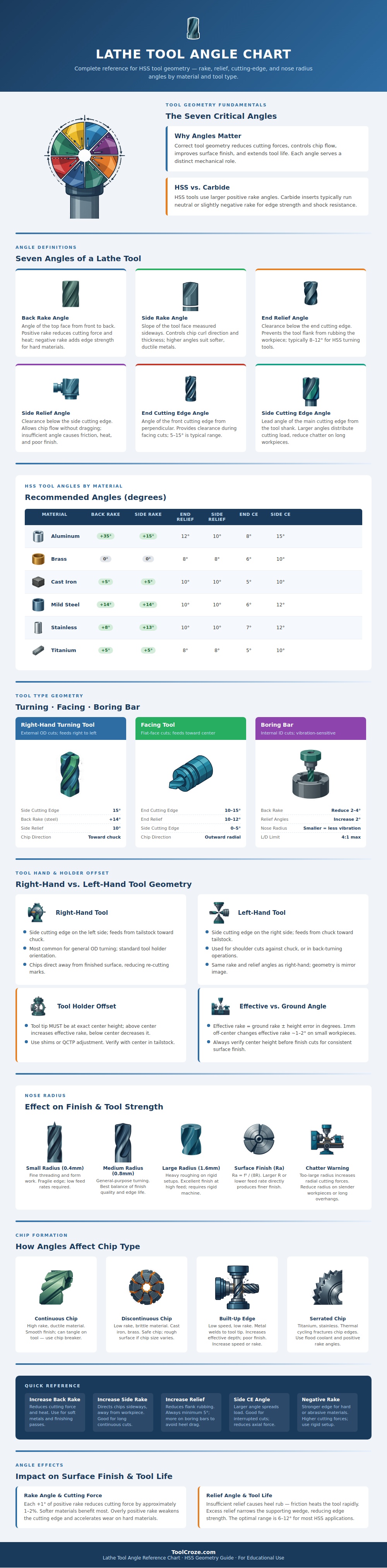
The infographic at top details those seven important angles and how they relate to controlling flow of chips (and thus heat) during machining. What most people who are new to this focus on, the thing you can see and obsess about, is rake angle, which doesn’t exist alone; rather, there are relief angles behind the cut and unseen by the eye. This create friction between the tool heel and the workpiece, which softens the tool faster then any cutting force could.
You’d want more of an aggressive positive rake angle on the tools you’re using for working on soft, gummy stuff such as brass or aluminum. You don’t want the material getting pushed into a tight corner where it will build pressure and tear. Instead, you want a high back rake that lets the material shear its way out cleanley. With something harder, like steel, you don’t want as strong of an edge, so you’ll reduce that positive rake down to even going neutral. You give up some cutting ease to get more strength at the tip. This ensure that if you put a lot of load on it, it doesn’t chip off.
New users don’t fully appreciate the importance of tool orientation. When feeding from the chuck end (the right side), the workpiece have the support of the tailstock or steady rest as necessary. For facing cuts close to the chuck jaws, though, it’s critical to use a left-hand tool… Otherwise you’ll just bash into the chuck hardware with a right hand tool.
The tool geometry are flipped; that’s why. But most importantly, the chip flow change entirely. Unless you compensate for this, you run the risk of trapping chips between workpiece and tool, which scratches up your finish. Avoiding that kind of damage is easy when you orient things correcty.
Surface quality is also changed slightly yet importently by nose radius. The bigger the radius, the more it will bridge over previous passes leaving a less obtrusive mark on surface. But the bigger the radius, the greater radial cutting force (which will promote chatter along long boring bars and/or on slender workpieces). It’s a rigidity-vs.-looks tradeoff, so reduce the nose radius if the machine rattle about and jack up the feed rate.
Lastly, monitor how you create chips to determine angle correctness. Good ductile cutting will produce continuous ribbon-type chips. Brittle material or an incorrect rake will produce discontinuous, crumbly chips. Built-up edge (where the metal welds to the tip of the tool) means your rake is insufficient on that particular alloy, or your speed are too slow.
All of these variables aren’t about remembering a chart, but rather learning the mechanics of shear. The metal speak to you, and when you’re right, you’ll walk away quietly as chips flow freely, knowing the geometry was solid. Understanding these interactions make machining more than a guessing game; it becomes a precise craft.
