Rebar Development Length Calculator
Estimate straight tension development, compression dowel length, standard hook embedment, and lap splice length using ACI-style variables for bar size, strength, cover, spacing, coating, casting position, and confinement.
📌Real Project Presets
⚙Development Length Inputs
Calculation Breakdown
🧱Current Material / Spec Grid
📊Rebar Size Reference
| Bar size | Diameter | Area | Weight | Common uses |
|---|---|---|---|---|
| #3 | 0.375 in / 9.5 mm | 0.11 in² | 0.376 lb/ft | Stirrups, light slabs |
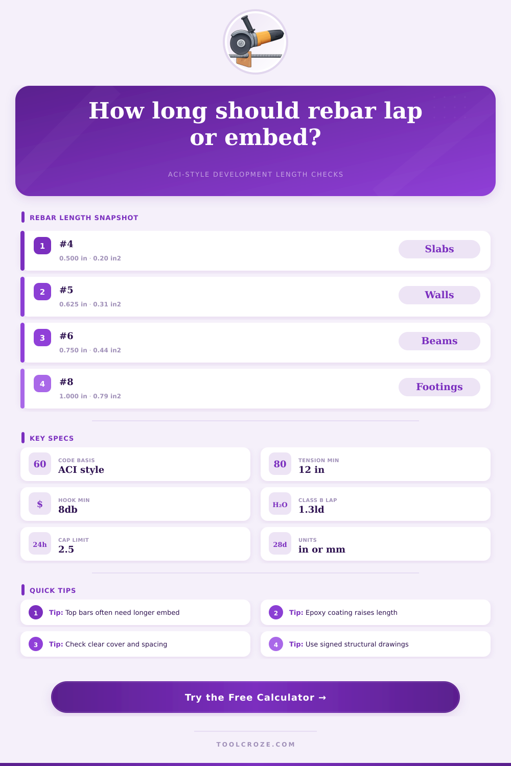
| #4 | 0.500 in / 12.7 mm | 0.20 in² | 0.668 lb/ft | Slabs, walls, patios |
| #5 | 0.625 in / 15.9 mm | 0.31 in² | 1.043 lb/ft | Footings, walls, beams |
| #6 | 0.750 in / 19.1 mm | 0.44 in² | 1.502 lb/ft | Beams, mats, columns |
| #8 | 1.000 in / 25.4 mm | 0.79 in² | 2.670 lb/ft | Heavy beams, piers |
🔢ACI-Style Modifier Reference
| Factor | Typical value | When it applies | Length effect |
|---|---|---|---|
| Top bar factor, ψt | 1.3 | More than 12 in fresh concrete cast below bar | Longer |
| Epoxy factor, ψe | 1.2 to 1.5 | Epoxy-coated reinforcement | Longer |
| Size factor, ψs | 0.8 or 1.0 | #6 and smaller may use 0.8 in tension | Shorter |
| Lightweight factor, lambda | 0.75 to 1.0 | Reduced concrete density | Longer |
| Confinement | 0.8 to 1.15 | Cover, ties, and bar spacing quality | Varies |
📏Cover, Spacing, and Confinement Guide
| Condition | cb estimate | Ktr use | Practical note |
|---|---|---|---|
| Interior mat bars | Min cover or half spacing | Often 0 | Usually controlled by spacing |
| Edge bars | Clear cover to side | Use with caution | May require longer length |
| Confined beam bars | Cover plus stirrup benefit | Can improve | Confirm tie spacing |
| Epoxy tight spacing | Low cb/db | Often ignored | Use 1.5 epoxy factor |
🔗Minimum and Splice Reference
| Check type | Base minimum | Multiplier | Use case |
|---|---|---|---|
| Straight tension | 12 in | 1.0ld | Embedment past critical section |
| Class A lap | 12 in | 1.0ld | Lower stress, well distributed bars |
| Class B lap | 12 in | 1.3ld | Most conservative common splice |
| Compression dowel | 8 in | ACI-style compression formula | Column and wall dowels |
| Standard hook | 8db and 6 in | Hook expression | Anchorage with 90 or 180 hook |
💡Detailing Tips
Reinforcement was supposed to stick in there like a thumbtack in foam. Everyone believes that. But it doesn’t; steel transfer load into the matrix around it through mechanical grip and friction alone. When that bond breaks, bar pulls out of the concrete long before structure is loaded up to capacity. This happens not because the steel isn’t strong enough, but because the concrete wasn’t holding onto it well enough.
Above, we’ve got a calculator to do all of this tricky ACI-style math for you. You don’t need to memorize all those coefficients for lightweight aggregate and epoxy coatings, but knowing the why behind the what help you design smarter.
Why Steel Needs Good Grip in Concrete
One example is casting position. Most people don’t think about it until its too late, but top bars needs a hell of a lot more development length than your bottom row. Fresh concrete settle below top bars, forming weak honeycomb pockets with poor bond strength. It’s a simple thing of physics, but it can be an expensive oversight.
Also on that form is request for spacing and cover data. It is not because the inspector wants you to be neat. But because this information play right back into the confinement factor. Are they too close together? Is it too deeply buried without enough transverse reinforcement? The concrete will split before steel gets a chance to yield.
That’s why there are reference tables on the page making distinctions between interior mat bars and edge conditions. Stirrups vs. Etc. A bar on an edge has no room to move sideways when stressed, so there must be more than one bar in the middle of a piece of concrete to make up for the loss of side support. This small bit of geometry make all the difference for safety.
Then there are material options that add variables. Black steel has better hold than epoxy coated rebar, which is slick. So what? Slick means lower friction, so for equal holding force you require longer embedment. The adjustment factors takes care of this in the calculator, but out in the field you must also honor the added length. If your material changes, you can’t simply slap down a normal detail and hope it’s good enough.
Another place that gut feeling doesn’t work out so well? With lap splices, two bars don’t just double distance of their development length. Stress is not spread evenly, and the concrete must carry the load across the joint from one bar to the next through a shared bond zone. Class B laps require more length because the bar spacing and stress concentration are not as effective. A standard hook may be all there is room for in this situation. The hook lengths, which the tool calculates based off the bar’s diameter and strength, will help you determine if you can still reach the end with straight embedment, or if you have to bend it around a corner.
The drawings are an idealization; reality is never that simple. The pour is not always high-quality concrete. Tolerances on bar placements varies slightly. To account for this, it makes sense to include a detailing allowance. This isn’t paranoia. This is a margin for error caused by mistakes that inevitablly happen during construction. Material cost for several more inches of embedment is basicly zero, but gives you much greater peace of mind in performance.
The takeaway is that length of development is a negotiation between the strength of the steel and how well it’s confined by the concrete. If you use high-strength rebar and surround it with poorly-confined and/or thinly-covered concrete, then what good does the strength of the rebar do? That’s why the output numbers, those displayed in the grid above, are so valuable. They’ll tell you exactly where this equation balances out for your situation. It tells you whether your setup will hold together when placed under stress.
Understand, however, that these aren’t rigid rules but limits set through code and testing to prevent the system from being too fragile to function. If something doesn’t feel right, look at your confinement inputs. More often than not, you will find that adding more clear cover or a stirrup can decreases the need for longer lengths rather than changing bar size.
Steel through concrete is about working with the concrete. It’s not so much about meeting some minimum amount on a piece of paper. But rather, is each bit of reinforcement doing its part and not slipping out? Does your beam splice have enough grip to keep it from slipping? Or do you need to check a footing dowel? Same principle applies. The strength of the bond has to be greater then the load trying to pull it apart. That’s how buildings hold up. And that’s what these calculations should of helped prove.