
Maybe it’s a weld at a T-joint where you’re standing there with a torch, questioning whether you just wasted your time or held the load with that quarter inch weld. It’s a familiar scenario for anyone who’s been on the shop floor. Knowing a little about the shape of fillet weld is what separates an overbuilt connection from a weak one. Knowing that doesn’t require being a structural engineer, but does mean knowing how leg size correlate to real world strength.
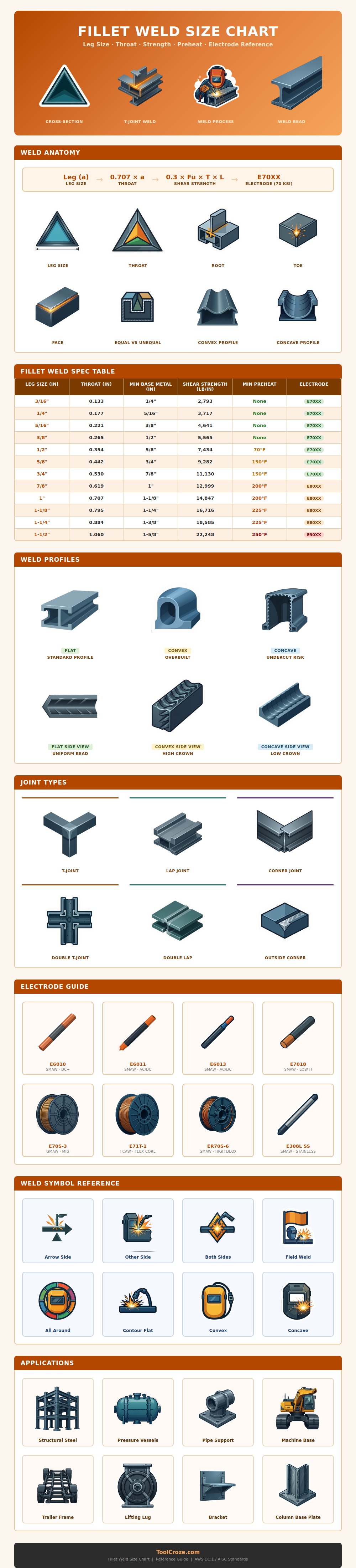
The chart above links leg dimensions directly to throat thickness. This measure shear resistance. The leg is distance from the root to the toe along each base metal face. You can easily measure this with a weld gauge or caliper. But when engineers compute strength, they don’t consider the leg, they consider the effective throat. The effective throat are about 70% of the leg for a standard fillet weld. This means, no matter what size bead you use, that throat-to-leg ratio remains consistent. If your leg size doubles, your throat double as well, which means the cross-sectional area resisting stress also doubles. Because of this correlation between weld size and capacity, small adjustments in weld size make big leaps in capability.
How to Make Strong Fillet Welds
For instance, a leg of only three sixteenths may look puny, but it resists shear of nearly two thousand eight hundred pounds per linear inch. That’s plenty enough for braces or light framing situations where fatigue isn’t a major concern. Then there are your heavier sections. The needs changes drastically here. Thick plate absorbs heat different than thin sheet metal because thick steel acts as a heat sink.
According to the infographic, when you get to a half-inch leg, it’s time for preheat. And it’s not some rule in a book I’m telling you about. It’s physics. Thick steel is a heat sink that sucks energy out of the weld pool at such a rapid pace that it actualy cools the joint too fast. When the steel cools rapidly, you end up with a hard and brittle microstructure that cracks on impact. You slow down the cool-down rate by preheating to 70-degrees or more which maintains a ductile joint. Messing around without this rule will leave you with cracked welds on base of heavy machinery. This is an expensive problem that costs you time cutting the piece out and doing it again.
Electrode selection is also important, although not necessarily for size. In the data, you’ll see the reference to E70XX, which denotes a tensile strength of seventy thousand PSI. It’s telling you how much you can stretch this sucker until it breaks. For welding most structural steels, E7018 is your stock stick electrode, offering deep penetration with resistance to cracking. On the MIG side, ER70S-3 wire takes the same type of duty. The trick is to match the base metal strength with your filler without going so strong as to waste money on more than needed. Mild steel accepts a high-strength rod fine. But why would you?
The weld profile surprisingly matters for longevity too. A weld with a convex shape appears large and proud. However, it adds height which cause stress concentrations on the toes of the weld. As the load tries to spread out over the face, it crowds into the sharp angles where the weld joins the plate. In contrast, a slightly concave or flat weld let the stress simply flow through the joint without any problems. This is actualy part of the reason why structural specs will frequently request that you grind down excessively convex beads. It is less impressive to look at, but it holds up longer under cyclic loading.
Preparation is everything. It applies to a corner connection, T-joint or lap joint. How well you fit it up determines whether the weld will be sucessful. Too large a gap means laying down more metal to fill the gap which adds heat and increases distortion. A tight joint results in cleaner beads and less filler. Engineering drawings contain the exact spots where the weld is to be placed and the contour desired. Knowing how to interpret these symbols prevents arguments at the job site.
A good weld is half calculation and half art. One part is knowing the math of whether something will stand up, and the other part are laying down a nice bead with a steady hand. When in doubt, pull out those throat calculations again. Sometimes a little more size on the legs makes all the difference… Sometimes a joint stands, sometimes a joint doesn’t. You should of checked your math first.
Pick your filler carefully. Keep an eye on your preheat temps, especially on thicker sections. Strive for a smooth weld profile. It does not need to be the largest weld, just the right weld.
