K-Factor Bend Calculator
Estimate neutral axis location, bend allowance, bend deduction, outside setback, flat blank length, and measured K-factor for sheet metal bending.
① K-Factor Presets
Choose a real shop-style setup, then adjust thickness, radius, angle, material, and bend allowance for your test bend.
② Bend Inputs
Bend Calculation Results
Formula Breakdown
③ Material / Spec Grid
④ Reference Tables
| Preset / material | Process | Typical R/T | Starting K |
|---|---|---|---|
| Mild steel cold rolled | Air bend | 0.8 to 1.5 | 0.33 to 0.40 |
| Mild steel cold rolled | Bottoming | 0.6 to 1.0 | 0.36 to 0.42 |
| 304 stainless steel | Air bend | 1.5 to 3.0 | 0.40 to 0.46 |
| 5052-H32 aluminum | Air bend | 1.0 to 2.0 | 0.40 to 0.44 |
| 6061-T6 aluminum | Large radius | 2.5 to 5.0 | 0.44 to 0.50 |
| Copper C110 | Bottoming | 0.5 to 1.2 | 0.34 to 0.39 |
| Brass 260 | Coining | 0.4 to 0.8 | 0.28 to 0.34 |
| Polycarbonate | Heat bend | 1.0 to 3.0 | 0.45 to 0.50 |
| Process type | What changes | Adjustment | Use note |
|---|---|---|---|
| Air bending | Radius floats with die opening | Medium K | Most press brake work |
| Bottoming | Material seats in the die | Slightly lower K | Repeatable with matched tools |
| Coining | High force thins bend zone | Lower K | Use only within tooling capacity |
| Roll bending | Large radius and low strain | Higher K | Best checked with a sample strip |
| Heated plastic | Softened bend line | Higher K | Cooling fixture affects result |
| Bend angle | Radians factor | Setback tangent | Quick check |
|---|---|---|---|
| 30° | 0.5236 | tan 15° = 0.268 | Small allowance |
| 45° | 0.7854 | tan 22.5° = 0.414 | Light flange bend |
| 90° | 1.5708 | tan 45° = 1.000 | Common bracket |
| 120° | 2.0944 | tan 60° = 1.732 | Open channel bend |
| Formula item | Expression | Input needed | Result meaning |
|---|---|---|---|
| Neutral axis offset | K x T | K-factor, thickness | Distance from inside face |
| Neutral axis radius | R + K x T | Radius, offset | Arc radius used for BA |
| Bend allowance | A x (R + K x T) | Angle in radians | Length added for bend arc |
| Outside setback | tan(A / 2) x (R + T) | Angle, radius, thickness | Virtual sharp setback |
| Bend deduction | 2 x OSSB - BA | Setback, allowance | Amount removed from flanges |
⑤ Practical Notes
Take a look at the press brake guy who grab a flat piece of metal and easily makes a perfect flange. At least that’s what it appears. On one hand he has a flat piece of metal; then on the other hand there’s a clean bracket that fit the drawing down to the millimeter. What’s the secret? That would be the k-factor, which indicate how much material compresses and how much material stretches while bending. Get the k-factor correct and everything go right, snapping into place just like designer imagined. Get it wrong and your part is too long or too short.
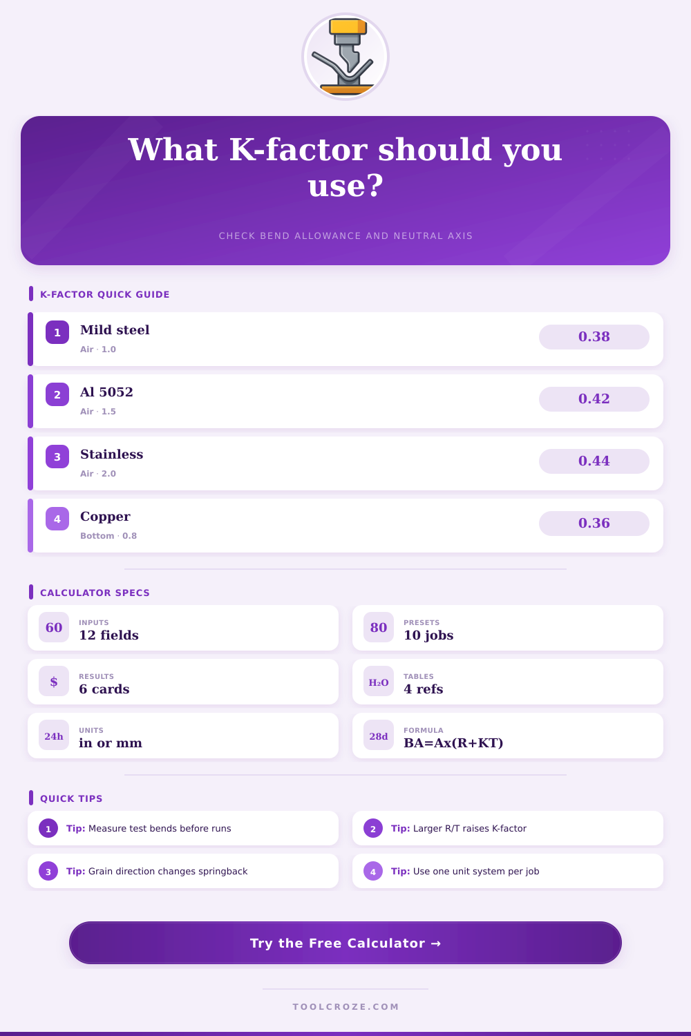
K-Factor: The k-factor represent the location of the neutral axis within the material. Think of it as an imaginary line in the material that does not stretch or shrink. For most sheet metals, this is located between 30% and 50% through material thickness. Several factors influence where the k-factor will be located: Grain direction, bending method (inside bend radius), material, and how the material are bent (i.e. Mild steel air-bent with a one-to-one radius may be closer to.38, while the same mild steel bottoming hard in the die would shift inward).
What Is K-Factor?
Aluminum usually land a little higher. Stainless steel often require a bigger number due to spring back. Mild steel air-bent with a one-to-one radius may be closer to.38, whereas the same mild steel bottoming hard in the die would shift toward the center. Aluminum usually lands a little higher. Stainless steel often requires a bigger number due to spring back.
When you enter actual numbers for your shop into the calculator, it will do math for you. Thickness matter more than most people admit. Even a slight variance in actual gauge can be enough to mess with your blank length and wreck a batch of panels. The other important factor is the inside radius, which affects how sharply the material are strained. Opening up the radius moves the neutral axis further out. Tightening the radius move it nearer the inside face. This add to the bend allowance required on the flat pattern.
The bend angle appears straightforward until you learn that it’s being converted into radians for use in most formulas behind the scenes. So bending at 90 degrees is easy; anything else will be different from what your eye predicts. And then there is the added wrinkle of grain direction. Generally, you’ll find that bending across the grain results in less springback and a slightly reduced k-factor. Bending with the grain is where things goes their own way. You typically has to adjust to get the result you want.
Where the tool excels is that one test bend becomes production knowledge. Form it up. Cut a little coupon out. Measure those leg precisely and type in what you saw as the real bend allowance. The calculator will work backward to tell you actual k-factor for your material, tooling, and machine combo. That number is worth gold for the rest of the job.
Off the shear, all those flat blanks are within a couple thousandths of perfection. Yet, somehow some of the common errors slip into the fold. Millimeters and inches gets mixed up within the same job. All calculations becomes ruined by this. Then there are those who don’t understand the distinction between bottoming versus air bending. They apply the same k-factor for each process. Or they forget that large radius bends shifts the neutral axis far beyond where a sharp punch hits during a press brake bend. This page is full of reference tables to prevent these mistakes before you reach the shear.
Remember: The k-factor is not some theoretical number. It’s actualy a record of what happened with your material on a certain day in certain conditions. Think about it as such and take your test parts seriously. When you do, the calculator won’t seem like a guessing game anymore but rather a trusted member of your shop team. The assembler won’t need to use shims or filing, and your flat patterns will be dead-on. You should of used this earlier.