Through-Tool Coolant Pressure Calculator
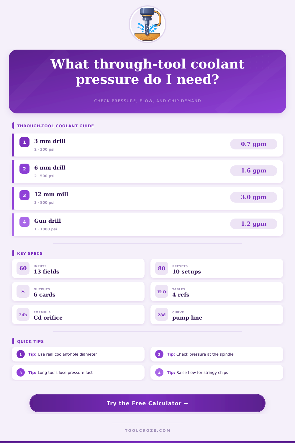
Estimate through-tool coolant pressure from coolant-hole diameter, hole count, target flow, pump curve, internal tool length loss, viscosity, material, and chip evacuation demand.
⚙ Unit System
🔧 Through-Tool Coolant Presets
📏 Pressure and Flow Inputs
Through-Tool Coolant Results
0
psi at pump0.0
0
psi available0
0
psi lossGood
📊 Material and Spec Grid
📘 Coolant-Hole Flow Reference
| Hole diameter | 300 psi per hole | 700 psi per hole | 1000 psi per hole |
|---|---|---|---|
| 0.020 in / 0.5 mm | 0.08 GPM | 0.12 GPM | 0.15 GPM |
| 0.032 in / 0.8 mm | 0.20 GPM | 0.31 GPM | 0.39 GPM |
| 0.040 in / 1.0 mm | 0.31 GPM | 0.48 GPM | 0.57 GPM |
| 0.055 in / 1.4 mm | 0.59 GPM | 0.90 GPM | 1.08 GPM |
| 0.078 in / 2.0 mm | 1.18 GPM | 1.81 GPM | 2.16 GPM |
⚖ Material and Chip Evacuation Demand
| Material | Pressure factor | Chip behavior | Coolant note |
|---|---|---|---|
| 6061 aluminum | 1.00 | Gummy, welding risk | Good flow washes chips |
| Mild steel | 1.10 | Moderate curl | Balanced pressure and volume |
| 4140 alloy steel | 1.18 | Tough segmented chips | Keep edge cooled |
| 304 stainless | 1.25 | Stringy and hot | More pressure for evacuation |
| Titanium | 1.45 | Hot, low conductivity | High pressure preferred |
| Nickel alloy | 1.55 | Severe heat load | Use strong filtration |
💧 Pump Curve Interpretation Table
| Curve region | What it means | Calculator handling | Practical adjustment |
|---|---|---|---|
| Below rated flow | Pressure near top of curve | Interpolates shutoff to rated | Usually pressure-rich |
| At rated point | Published pump condition | Uses rated pressure and flow | Best comparison point |
| Above rated flow | Pressure falls quickly | Interpolates rated to open flow | Reduce demand or add pump |
| Beyond open flow | Pump cannot supply volume | Flags poor curve fit | Use larger holes only with capacity |
🔧 Real Through-Tool Preset Specs
| Preset | Tool holes | Flow target | Typical use |
|---|---|---|---|
| 3 mm carbide drill | 2 x 0.020 in | 0.35 GPM | Small aluminum holes |
| 6 mm steel drill | 2 x 0.032 in | 0.75 GPM | Production steel drilling |
| 1 in U-drill | 2 x 0.078 in | 3.2 GPM | Indexable rough holes |
| Stainless deep drill | 2 x 0.040 in | 1.2 GPM | Long 304 holes |
| Through end mill | 3 x 0.055 in | 2.4 GPM | Chip wash in pockets |
| Gun drill | 1 x 0.063 in | 1.1 GPM | Single-lip drilling |
✓ Shop Tips
This is a through-tool coolant pressure estimate. This calculator estimates what is happening at cutting edge. It combines several factor: chip evacuation demand, material behavior, coolant viscosity, length losses from tool, pump curve capacity, and orifice flow.
Coolant plays a critical role in avoiding jammed flutes when you push an end mill or through-tool drill into a cut. A lot of pump pressure isn’t helpful if it dissapears before getting to the cutting edge. Machinists who run high-pressure systems obsess over every variable the calculator handles. They follow each variable the calculator takes into account. They watch internal length, hole diameter, viscosity, chip behavior, etc.
How This Coolant Pressure Calculator Works
Titanium resists breakage. Stainless steel strings. Those variables shifts. The coolant holes are where you’ve got to begin.” Everyone assumes that whatever diameter a drill bit is, it will equal size of passage inside the tool, “but it never does. Most people measure the drill diameter and assume the internal passages match, but they rarely do; for example, a 6 mm drill might carry two 0.8 mm holes, while a larger indexable tool can hide passages closer to 2 mm. Flow isn’t linear; it’s squared. Doubling the hole diameter result in about four times as much flow at the same pressure. Every other calculation crumbles if you goof on the diameter.”
The more length, the greater the compounding effect. Most shops fail to realize this. As flow speed increases, losing every inch inside tool body, extension, and holder reduces pressure significantly. Hundreds of psi is lost as a gun drill travels down its fourteen-inch depth before coolant reaches cutting edge. That’s why the calculator accounts for it automatically. You no longer have to guess how much pressure is really being delivered (e.g., 1000 psi pump = 650 psi at tip).
The drum label is secondary; it’s all about the coolant type. Synthetics are thin while straight oils are thick. This viscosity change impact the Reynolds number in those tiny orifices. It also affects how much pump pressure are needed to move the same volume. The tool takes this into account. But the lesson here is a bit simpler in practice. Switching from oil to emulsion without changing hole size or pressure will cause one of two things: it will either overload the pump or starve the cut.
There’s an unseen tax, too: how the material behaves. Titanium and nickel alloys demand pressure to overcome low thermal conductivity and heat at cutting edge. Aluminum wants volume to flush gummy chips before they weld. It’s a heat issue at the cutting edge. When using stringy 304 steel or blind holes, you must multiply the entire pressure target by the demand setting for chip evacuation. Suddenly it’s not just cooling but pneumatic chip removal disguised as a coolant process.
What catches people by surprise is the pump curve. That 2.5 gpm/700 psi pump won’t deliver both simultaneously. Higher flow mean lower pressure. The whole curve is drawn on the calculator so you can see where your desired flow lies. Is it at high end of the safe midrange? Is it near the knee (where things all go downhill)? Or is it already outside the open-flow limit of the pump?
Knowing that margin, literal seeing it as numbers. Alters the conversation. It turns what was “I think we need more pressure,” into “We need a different pump or bigger holes.” This doesn’t replace a spindle gauge. What the math won’t account for can be stolen by filters, fittings and worn seals at the rotary union where it all meets reality. But knowing where to turn the dial comes from doing the math first. And it lets you know when it’s time to start thinking about completely re-designing the plumbing inside that tool.
Coolant through the tool isn’t about chasing a number on the psi gauge. Coolant through tool is getting the correct amount of volume and pressure at the point of cut before the chip can be a problem. Before it gets a chance. If you do that you’ll see better finishes and longer tool life. It will also quiet down the sound of the machine as if it’s trying to eat itself. Miss that mark and even the most luxurios high-pressure system turns into an overpriced path to scrap.