Drilling Torque Calculator
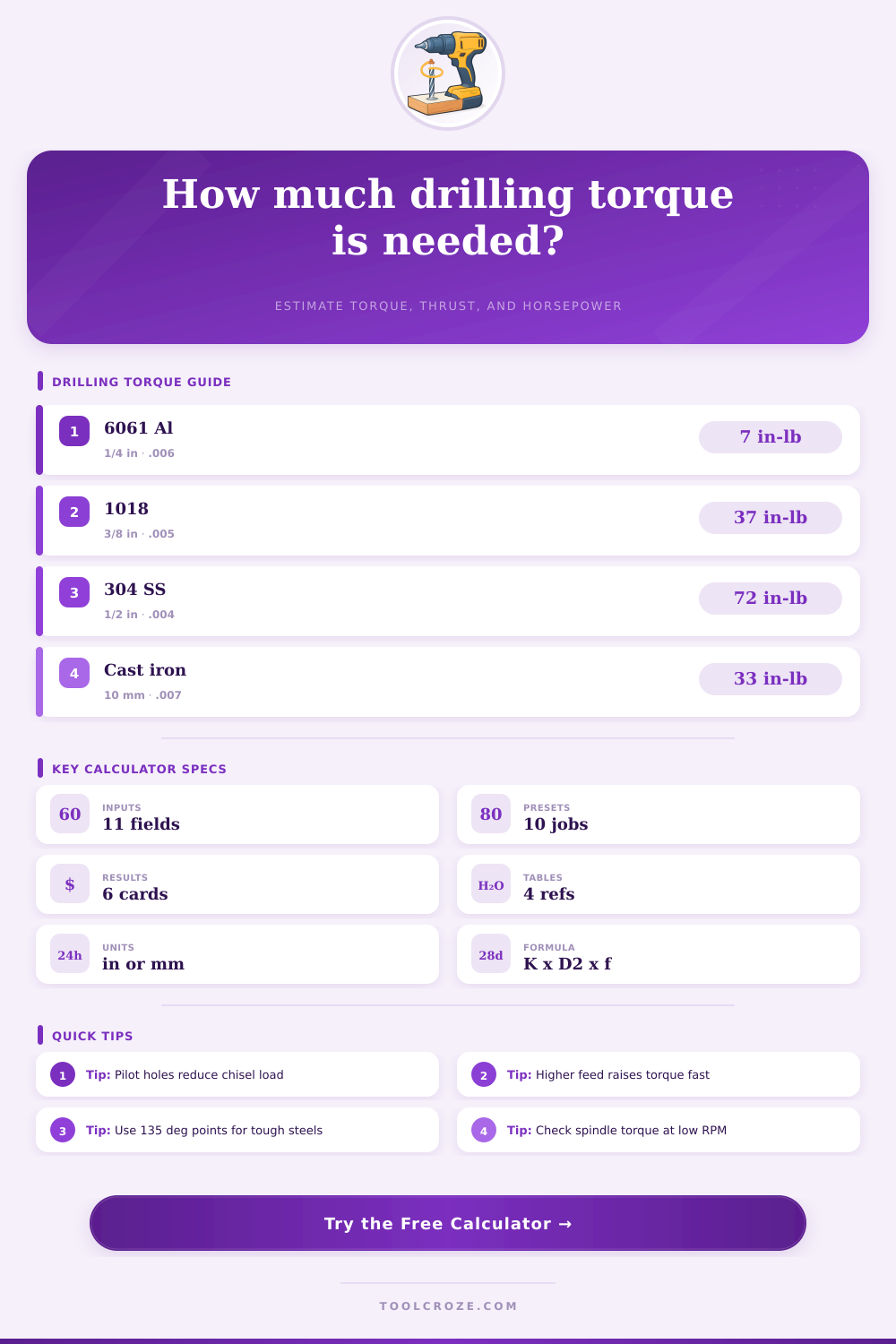
Estimate drilling torque, thrust load, spindle horsepower, pilot hole relief, and point angle effects from drill diameter, feed per revolution, RPM, and material torque coefficient.
Named Drilling Presets
Inputs
Drilling Load Results
Calculation Breakdown
Selected Material Spec Grid
Material Torque Coefficient Reference
| Material | Torque coefficient K | HSS SFM range | Feed note |
|---|---|---|---|
| 6061 aluminum | 42000 to 55000 | 200 to 350 | Can take heavier feed with chip evacuation. |
| 1018 mild steel | 95000 to 115000 | 70 to 110 | Good baseline for general drilling torque. |
| 4140 prehard steel | 125000 to 155000 | 45 to 75 | Use rigid setup and controlled feed. |
| 304 stainless steel | 150000 to 185000 | 25 to 55 | Do not rub; keep positive feed. |
| Gray cast iron | 75000 to 95000 | 70 to 120 | Dry dust needs extraction and guarding. |
| Bearing bronze | 65000 to 85000 | 90 to 160 | Sharp geometry reduces grabbing. |
| Ti-6Al-4V titanium | 170000 to 220000 | 20 to 45 | High torque and heat; use coolant. |
| Acrylic plastic | 22000 to 32000 | 100 to 220 | Reduce heat and avoid aggressive breakthrough. |
Drill Size, Feed, and Load Examples
| Drill size | Light feed | Medium feed | Heavy feed |
|---|---|---|---|
| 1/8 in or 3 mm | .0015 in/rev | .0025 in/rev | .0040 in/rev |
| 1/4 in or 6 mm | .0030 in/rev | .0050 in/rev | .0080 in/rev |
| 3/8 in or 10 mm | .0040 in/rev | .0065 in/rev | .0100 in/rev |
| 1/2 in or 13 mm | .0050 in/rev | .0080 in/rev | .0120 in/rev |
| 3/4 in or 19 mm | .0060 in/rev | .0100 in/rev | .0160 in/rev |
| 1 in or 25 mm | .0080 in/rev | .0130 in/rev | .0200 in/rev |
Pilot Hole and Point Angle Factors
| Condition | Typical factor | Torque effect | Shop note |
|---|---|---|---|
| No pilot hole | 1.00x | Full chisel edge load | Best estimate for solid drilling. |
| Pilot at 25 percent D | 0.95x | Small reduction | Helps center larger drills. |
| Pilot at 40 percent D | 0.85x | Moderate reduction | Common for hand-fed setups. |
| Pilot at 60 percent D | 0.70x | Large reduction | Watch drill corner loading. |
| 118 degree point | 1.00x | Baseline | General purpose point geometry. |
| 135 degree split point | 0.92x | Lower thrust | Useful in alloy and stainless steel. |
Preset Setup Details
| Preset | Diameter | Feed per rev | RPM and note |
|---|---|---|---|
| 1/4 in 6061 HSS | 0.250 in | 0.0060 in/rev | 3000 RPM, no pilot |
| 3/8 in 1018 Steel | 0.375 in | 0.0050 in/rev | 850 RPM, through hole |
| 1/2 in 304 Cobalt | 0.500 in | 0.0040 in/rev | 275 RPM, 135 degree point |
| 10 mm Gray Iron | 10 mm | 0.18 mm/rev | 900 RPM, dry drilling reference |
| #7 Tap Drill 1018 | 0.201 in | 0.0030 in/rev | 1200 RPM, blind hole |
| 3/4 in Piloted Steel | 0.750 in | 0.0090 in/rev | 320 RPM, 1/4 in pilot |
Drilling Torque Tips
Drilling torque is what separates a smooth job from a wrecked spindle or broken tool. That sudden tug, which feels like the cut’s starting to protest, is telling you something is working harder then it should. This is where numbers come into play, putting that feeling into the calculator on this page to help with planning rather than guessing.
Most of the torque in drilling arise from the force on the cutting lips plus resistance of the material against the chisel edge. The basic relationship is simple enough: torque = diameter squared x feed per revolution x some sort of material coefficient. You see that squared term? It’s what means that going up one size (e.g., from a quarter-inch to a half-inch) doesn’t simply double your load… It quadruples it! Feed matter nearly as much; indeed, push harder and torque climb right along with it. When chatter begins, feed is the first thing to adjust for, almost by definition.
Why Drilling Torque Matters
Each material are different and fights back differently. Some, like aluminum, chip easy and require high feed rates and fast speeds. Others, stainless steel; will work-harden if you let them rub. These require lower surface speed and positive chip load to keep from turning your drill into a dull tool. Still others is more of an odd mix: titanium has great torque but terrible thermal conductivity (so that heat just hangs out right at the cutting edge). These are all things the tool captures in its reference tables, but there’s no need to have to memorize each coefficient.
The other wrinkle is point geometry. 118 degrees is good, but 135 degrees cut through tougher alloy more easily under thrust load. That counts if you’re hand-feeding or have a light machine. Pilot holes matter as well by eliminating middle section that doesn’t do any real cutting anyway, so a well-sized pilot will help keep the drill in place and drop the torque noticeably. Don’t go too big on the pilot though or you’ll starve the outside corners of work and invite vibration. All of this geometry is folded into an adjusted result on the calculator where you can see the tradeoffs at a glance.
Torque and rpm are used to calculate how much horsepower you need, but what good is that if your spindle doesn’t have enough? Efficiency factors is displayed just below the total power figure; most drives, gears, or belts reduce power by surprise amounts in shops. Everyone talks about torque, yet thrust may be its little brother that’s overlooked: It can raise a poorly clamped part or deflect a long drill if nobody pays attention. Both figures are given to you on the tool, to see complete picture of the load.
In the real world, there is variables that the math doesn’t see. A nice steady cut in a deep hole becomes a packed flute that suddenly spikes torque as chip evacuation fails. Peck cycles help, but they add time. Coolant makes a bigger difference than most admit. It keeps the cutting edge from welding itself to the workpiece, especially on steels and titanium. And machine itself matters. A rigid CNC behaves different than a wobbly old drill press, even when the calculator says the loads are identical.
For me the best shops use the calculator, but as a trusted second opinion, not as a gospel. They run it through, then hear it in their head and tweak accordingly. That’s what makes spindles happy and tools sharp. If you get the torque right everything downstream gets easy. You should of used the calculator more often to avoid mistakes like this. It would of saved time too.
Most modern machines can absorbs any amount if you aren’t careful, but a sudden spike in torque could dissapear your progress. Actually, it is naturaly better to be safe. One might recieve a broken bit if they are not careful with the luxurius finish they want. It depends based off how much weight you put on the machine.