Adaptive Clearing Engagement Calculator
Estimate radial engagement, cutter immersion, chip thinning feed adjustment, slot passes, material removal rate, and machine load for adaptive CNC clearing paths.
Adaptive Clearing Results
Full Calculation Breakdown
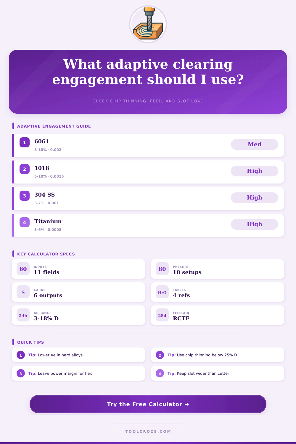
| Material | Adaptive Ae Range | Target SFM | Base Chip Load | HP per in^3/min |
|---|---|---|---|---|
| Aluminum 6061-T6 | 8% to 18% D | 800 to 1000 | 0.0015 to 0.0040 in | 0.30 to 0.45 |
| Aluminum 7075-T6 | 7% to 15% D | 700 to 900 | 0.0013 to 0.0035 in | 0.35 to 0.50 |
| Mild steel 1018 | 5% to 10% D | 250 to 350 | 0.0008 to 0.0022 in | 0.75 to 1.10 |
| 4140 prehard steel | 4% to 8% D | 180 to 280 | 0.0006 to 0.0018 in | 0.95 to 1.30 |
| 304 stainless steel | 3% to 7% D | 140 to 220 | 0.0005 to 0.0015 in | 1.05 to 1.45 |
| Titanium Ti-6Al-4V | 3% to 6% D | 110 to 180 | 0.0004 to 0.0012 in | 1.10 to 1.55 |
| Brass C360 | 8% to 16% D | 500 to 750 | 0.0012 to 0.0030 in | 0.40 to 0.60 |
| Acetal plastic | 10% to 25% D | 600 to 1000 | 0.0020 to 0.0060 in | 0.10 to 0.25 |
| Radial Stepover | Immersion Angle | Chip Thinning Factor | Common Use | Feed Note |
|---|---|---|---|---|
| 3% D | 28.1 deg | 2.13x | Titanium and stainless | Use only when toolpath is smooth |
| 5% D | 36.9 deg | 1.67x | Hard steel roughing | Good starting point for tough alloys |
| 8% D | 47.2 deg | 1.37x | General steel clearing | Balance between feed and load |
| 10% D | 53.1 deg | 1.25x | Aluminum and mild steel | Common adaptive baseline |
| 15% D | 66.4 deg | 1.09x | Rigid aluminum roughing | Watch power and chip evacuation |
| 20% D | 78.5 deg | 1.02x | High rigidity machines | Chip thinning is nearly gone |
| Setup Condition | Feed Factor | Recommended Ae | Axial Depth Cue | Risk Signal |
|---|---|---|---|---|
| Light desktop CNC | 0.65x | 3% to 8% D | 0.5D to 1.0D | Frame flex or chatter |
| Benchtop mill | 0.80x | 4% to 10% D | 0.75D to 1.5D | Toolholder slip |
| Light VMC | 0.92x | 5% to 14% D | 1.0D to 2.0D | Corner load spikes |
| Rigid VMC | 1.00x | 6% to 18% D | 1.5D to 3.0D | Spindle load climb |
| High performance VMC | 1.10x | 8% to 22% D | 2.0D to 4.0D | Thermal growth |
| Cutter Type | Typical Flutes | Best Materials | Adaptive Note | Chip Evacuation |
|---|---|---|---|---|
| 2 flute carbide end mill | 2 | Aluminum, plastics | High chip space for deep pockets | Excellent |
| 3 flute aluminum end mill | 3 | 6061, 7075, brass | Good feed with balanced clearance | Very good |
| 4 flute variable helix | 4 | Steel, stainless | Stable at low radial engagement | Good with air blast |
| 5 flute rougher-finisher | 5 | Steel and titanium | Strong core, moderate chip room | Moderate |
| Compression spiral router | 2 | Hardwood, plywood | Use shallow Ae to reduce burning | Good with dust pickup |
Adaptive clearing is about changing your approach to contour and rough pocket work. Rather than using full slotting cuts and burying a cutter, you maintain constant and lower radial engagement. Full slotting cuts can break tools and shake the machine. You locate that “sweet spot”. The point at which the tool remains productive but does not overload the spindle nor cause chatter. In doing so, you run longer, faster and deeper then traditional methods would allow.
The primary challenge is balancing chip load with radial engagement. If a cutter has less than twenty percent contact with the material, the chip thickness will be less than the programmed feed rate per tooth. It’s rubbing rather than cutting on the edges. This dulls the tool quicky and generates heat. Calculating chip thinning tells you by how much you should of up your feed rate. The idea is to set the feed such that the actual thickness of the chip matches what the tool can handle. In other words, it will clean out without smoking or needing to be thinned further. Light engagement require this adjustment.
How to Use Adaptive Clearing Safely
The other factor is material. Stainless steel and titanium generate heat readily so they requires single-digit percentages. They will perform well if fed aggressively, but aluminum can handle a lot more engagement; tens of percentage points. By choosing an alloy, the calculator calculates those relationships for you. It accounts for how spindle speed, depth, stepover, and the type of alloy interact. That way you won’t be left guessing whether you’re being reckless or bold.
All decisions is about rigidity. If you have a lightweight desktop mill, it’s going to be less rigid than a full VMC. Even if the math say you’re good, you need to cut feed rates and in some cases depth as well. This is made worse by tool stickout. The further your tool sticks out, the more it deflects and the less weight it can safely hold. Adding a small amount to a conservative reduction factor is inexpensive insurance. It prevents leaving performance on the table, and protects you from seeing a part shift or watching a tool walk away.
The plan shape includes narrow pockets or slots that limit the width of the cutter. If it’s barely big enough for the feature, there isn’t much space for gradual stepping over. More passes offset the tool and remove less material. The calculator will warn you soon (and the toolpath engine tries), so the strategy is not efficient. In some cases, it’s better to rough with a smaller tool. In other places, you may give up a couple conventional pass.
People miss that true corner engagement is not the same as programmed stepover. Inside corners, even with adaptive toolpaths trying to hold a consistent load, can still see spikes in force. A little extra stock allowance for finish pass helps here. No matter what corner transitions there are, the calculator doesn’t model them all. But it will give you a reliabl idea of the average load before you ever touch the machine.
The same feed variables is used for horsepower estimate, material removal rates and feed adjustment. Looking at all three help determine whether this is in line with what you’re running now or something stiffer is required. For example, by reducing engagement from 12 to 8%, you can double your axial depth without exceeding the spindle’s capacity. These tradeoffs shift the cycle time. Respect physics, get adaptive clearing rewards. Numbers don’t take the place of judgment; they point your way. Thoughtfully dial in the parameters and leave yourself some wiggle room for what you didn’t think of. Smooth loads and efficient metal removal are the reward. Parts come off the table faster then before. All that careful calculation is so well worth it because it provides this level of confidence.