CNC Plunge Rate Calculator
Estimate a practical plunge feed from cutter diameter, flutes, chip load, spindle RPM, material, tool style, entry mode, depth, and chip evacuation.
⚙️Named CNC Plunge Presets
📏Plunge Inputs
Calculated CNC Plunge Setup
🏭Selected Material and Tool Grid
📊Material Plunge Reference
| Material | Common Tool | Chip Load Range | Plunge Percent | Preferred Entry |
|---|---|---|---|---|
| 6061 Aluminum | 2-3 flute carbide end mill | 0.0015-0.0060 in | 20-45% | Ramp or helical |
| Hardwood | 2 flute spiral router bit | 0.0020-0.0070 in | 30-60% | Ramp or straight |
| Plywood | Compression or downcut bit | 0.0020-0.0060 in | 25-55% | Ramp |
| MDF | Upcut or compression router bit | 0.0030-0.0090 in | 35-65% | Straight or ramp |
| Mild Steel | HSS drill or carbide end mill | 0.0007-0.0025 in | 10-25% | Peck or ramp |
| Stainless Steel | Coated carbide end mill | 0.0004-0.0018 in | 8-18% | Peck or helical |
| Acrylic | O-flute or polished carbide | 0.0015-0.0050 in | 25-45% | Ramp |
| Machining Foam | Ball nose or router cutter | 0.0060-0.0200 in | 45-80% | Straight or ramp |
🔧Tool Type Adjustment Table
| Tool Type | Typical Use | Plunge Factor | Chip Evacuation Need | Note |
|---|---|---|---|---|
| Carbide End Mill | Metals, plastics, wood | 1.00 | Moderate | Best with ramp or helix in pockets |
| HSS End Mill | General metal cutting | 0.82 | High | Reduce heat and avoid rubbing |
| Router Bit | Wood, MDF, plastics | 1.08 | High | Needs air or dust extraction |
| Compression Bit | Plywood, melamine | 0.92 | High | Respect upcut section length |
| Twist Drill | Round holes | 0.70 | Very high | Use pecking for depth and metals |
| Ball Nose Cutter | 3D surfacing and foam | 0.88 | Moderate | Center tip has low surface speed |
| Roughing End Mill | Aggressive clearing | 1.12 | High | Works well with chip thinning margin |
| Micro End Mill | Fine detail and small pockets | 0.55 | Very high | Deflection limits the plunge rate |
📐Mode and Evacuation Reference
| Entry Mode | Multiplier | Best For | Watch Point | Starter Setting |
|---|---|---|---|---|
| Ramp Entry | 1.00 | Pockets, slots, wood, aluminum | Ramp length and step depth | 30-45% |
| Straight Plunge | 0.72 | Open chips and short depths | Center cutting ability | 20-35% |
| Straight Peck | 0.62 | Drilling, steel, deep holes | Dwell and chip packing | 10-25% |
| Helical Entry | 1.10 | End mills entering pockets | Helix diameter clearance | 30-50% |
📋Named CNC Plunge Starting Points
| Preset | Diameter | RPM | Chip Load | Plunge Target |
|---|---|---|---|---|
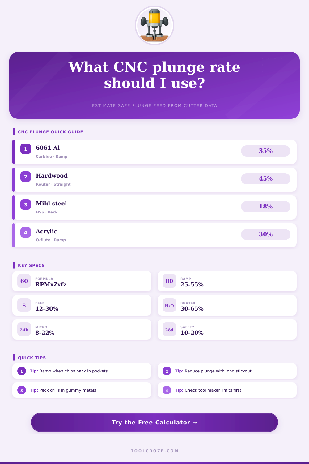
| 1/4 Carbide 6061 Ramp | 0.250 in | 18000 | 0.0020 in | 35% |
| 1/8 Router Bit MDF Pocket | 0.125 in | 21000 | 0.0030 in | 50% |
| 6 mm Plywood Slot Drill | 6.0 mm | 18000 | 0.070 mm | 40% |
| 3/8 HSS Mild Steel Peck | 0.375 in | 1200 | 0.0015 in | 18% |
| 1/2 Carbide 6061 Helical | 0.500 in | 12000 | 0.0035 in | 32% |
| 4 mm Acrylic O-Flute Ramp | 4.0 mm | 16000 | 0.045 mm | 30% |
| 10 mm Hardwood Rougher | 10.0 mm | 16000 | 0.110 mm | 48% |
| 5/16 Compression Melamine | 0.3125 in | 18000 | 0.0030 in | 38% |
💡Plunge Rate Tips
To find a practical entry feed, you must considers several factors. These include chip load, RPM, cutter geometry, depth, entry mode, chip evacuation, material, and tool type. This calculation allow for safer setup choices.
Plunging straight down into material sounds easy until your end mill starts screaming or deflects. Sometimes it break altogether or ruins the workpiece. In those cases, it’s all about that one number, how quickly does the tool axially feed? Get this wrong and you’ll chatter, create a poor surface finish or something worse. Set it right, and the rest of cut usually behaves well.
How to Find the Right Plunge Rate
For plunging small tools or working with unfamiliar material, understanding plunge rate is more important then most machinists will admit. But here’s the rub: Plunge, at least for us, isn’t just some percent off our XY feed. It’s a function of the way cutter engages the material, how well it escapes chips, and how rigid the entire set-up is.
For example, a carbide end mill plunged into 6061 aluminum can endure much more aggressive plunge than the exact same one sunk in mild steel. Likewise, a router bit working in MDF will behave different than one working in hardwood because both are non-uniform materials that quickly generate heat. When you input your details, the calculator figures out those relations behind the scenes. What used to be a guessing game becomes more accurate and moves beyond conservative rules of thumb.
Then think about tool stickout. With that extended reach, your safe plunging depth decrease when you extend the tool another inch. That’s because longer tools deflect more, which makes them problematic right off the bat when plunging. But it also depends on what mode you’re using. Helical or ramping entries mean you can go faster since you’re not forcing the tool to fight its full diameter all the way from start.
Metals get even trickier here; straight plunges requires greater care due to their quick chip packing. Add peck drilling into the mix, and it subdivides the action into shorter bursts followed by retraction to clear away waste. All of these are not small modifications, as they all take into account actual forces involved at the cutting edge.
A lot of this comes down to material behavior. Stainless is tough; soft foams and some type of wood will forgive aggressive plunges where your tools would of been toast. Some acrylics melt if not handled carefuly; others crack easily.
You’ll see charts on the page called “chip load.” You’ll also see “plunge %” and “best entry method,” too. These are all approximate ranges for each combination of tool type and material. They’re there to provide context when you enter a number. For example, a roughing end mill (roughly the same size as one micro tool) can often take a deeper plunge because it has more chip clearance and is stronger.
The headline plunge rate is just part of the story that comes out of the tool. You can see how many pecks it will take, how long it should take (with that machine), and how much material you’ll remove as well. Surface speed is also a sanity check on whether your RPM choice was reasonable to begin with. Together they provides a picture of the whole operation versus just one variable.
Situational: Plunge rate is typically situational, but people treat it like it’s not. They’ll use a feed rate copied off one job onto another without considering depth, coolant or stickout. Or they assume all tools cuts equally well at the center without any consideration of walking/chattering. A conservative plunge rate is a safe bet; adjust it based off chip appearance, load, and sound. Experience and calculation meet here.
So all things considered, what’s the best plunge rate? Whatever allows you to make a confident cut without any drama. That’s what the calculator provides, that starting point based on those real-world relationships between geometry, material and speed. After that, you must use your judgment, eyes, and ears to finish the task.