Engraving Bit Feed and Speed Calculator
Calculate V-bit effective diameter, RPM, feed rate, pass count, cutting time, and chip load for CNC engraving.
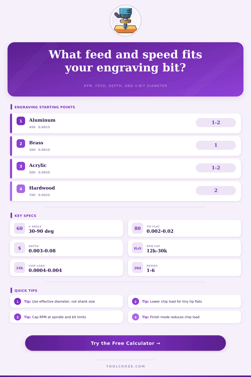
The grid updates from the selected material and compares the entered chip load against common engraving starting ranges.
| Material | Typical SFM | Chip Load Range | Finish Bias | Coolant / Air |
|---|---|---|---|---|
| Anodized aluminum | 350-650 | 0.0008-0.0030 in | Keep chips moving | Mist or strong air |
| Free-machining brass | 200-450 | 0.0005-0.0020 in | Short chips, clean edges | Air, light oil optional |
| 304 stainless steel | 70-160 | 0.0003-0.0012 in | Reduce rubbing | Coolant preferred |
| Hardwood lettering | 500-900 | 0.0010-0.0040 in | Grain-safe feed | Dust extraction |
| Cast acrylic | 350-800 | 0.0010-0.0040 in | Avoid melting | Air blast |
| FR-4 PCB | 250-550 | 0.0004-0.0015 in | Control tip wear | Dust extraction |
| Bit Style | Tip Flat | Included Angle | Best Use | Practical Note |
|---|---|---|---|---|
| 30° micro V-bit | 0.002-0.006 in | 30° | PCB, tiny serials | Very sensitive to runout |
| 45° detail V-bit | 0.003-0.010 in | 45° | Small tags, fine text | Balanced width and depth |
| 60° general V-bit | 0.005-0.020 in | 60° | Nameplates, signs | Good first test setting |
| 90° bold V-bit | 0.010-0.030 in | 90° | Wide lettering, fills | Diameter grows quickly |
| Single flute engraver | 0.004-0.020 in | 30-60° | Aluminum, plastic | Clears gummy chips well |
| Diamond drag point | Spring point | No cutting SFM | Drag marking metal | Feed by pressure, not chip load |
| Included Angle | Depth 0.005 in | Depth 0.015 in | Depth 0.030 in | Geometry Behavior |
|---|---|---|---|---|
| 30° | +0.0027 in | +0.0080 in | +0.0161 in | Narrow, deep-looking marks |
| 45° | +0.0041 in | +0.0124 in | +0.0249 in | Fine lettering with control |
| 60° | +0.0058 in | +0.0173 in | +0.0346 in | Common general engraving |
| 90° | +0.0100 in | +0.0300 in | +0.0600 in | Wide top line at shallow depth |
| Scenario | Material | Typical Bit | Depth | Watch Point |
|---|---|---|---|---|
| Anodized tag | Aluminum | 60°, 0.005 tip | 0.006-0.012 in | Clear oxide chips |
| Brass nameplate | C360 brass | 45°, 0.003 tip | 0.004-0.010 in | Avoid rubbing at low feed |
| Hardwood sign | Maple or oak | 60°, 0.010 tip | 0.020-0.060 in | Grain tearout |
| PCB trace isolation | FR-4 copper | 30°, 0.002 tip | 0.003-0.006 in | Flatness and runout |
| Stainless serial | 304 stainless | 45°, 0.005 tip | 0.002-0.006 in | Heat and work hardening |
The tiny engraving bit appears innocent enough in the collet, yet all the difference between a good logo and no logo is sometimes just what number you enter into the CNC machine. Run the spindle at the wrong speed and you end up with a burned spot, or worse, chatter. Feed too slowly and you’ll rub the material rather then cut it, resulting in fuzzy edges that destroy fine lettering.
This pressure means engraving needs its own set of speed and feed rules, different than those used for bulk milling. That’s what the V-bit does. Its shape changes diameter with increasing depth of cut. At fifteen thousandths deep, that 60-degree bit may be just.017 inches wide across its tips, following a.005-inch tip flat. Push it deeper and the effective cutting diameter grows fast.
How to Choose Speed and Feed for Engraving
That’s how fast the cutting diameter increases. This calculator automaticly converts for you, you don’t need to pause and do your trig on scratch paper. It also gently prompts you to consider working diameter at cutting depth (not the shank) since that’s what you’re measuring for surface speed.
Add in another wrinkle: how different materials behave. If you push too hard on hardwood, it will tear along grain. If you go too lightly on aluminum, it will weld onto your cutting edge. Stainless steel is tough because it work-hardens the instant it gets warm. Your tool lets you adjust chip load at the base and surface feet per minute for your particular material. This helps you control this behavior.
It then factors in whether you’re cutting a deep mark (roughing out). It also considers if you’re carving lettering where the top and bottom is equal, or trying to make a cut so small it doesn’t even disturb surface. The other quiet, but smart feature is finish mode.
When making a delicate engraving pass, there’s no need for same level of aggression as if clearing out a pocket. In polish setting, the calculator will scale chip load back to fifty-five percent to protect your precious final passes while leaving you with clean side walls. This happens without forcing you to drop your spindle speed so low that it begin to rub. You get a smooth cut that keeps heat manageable and extends tool life.
Most hobbyists don’t realize that planning depth per pass is far more important. Taking one big cut with a sharp pointed V-bit puts enormous side pressure on the bit, which will deflect the spindle or break its tip. Taking several shallow cuts lowers the load and makes it more accurate (especially when cutting metal). This is why calculator breaks down how many times to do this. Then, it will recalculate new effective diameter of each following layer. This keeps both feed and RPM appropriate for the whole job.
The final pieces of the puzzle are path length and stepover. If you multiply the pass time by the number of passes, your actual cutting time can jump from seconds to minutes on a long, complicated logo. If you know how many minutes ahead of time, you can choose to run it fast with a little more tip or slow down. Stepover determines the smoothness of the filled areas. Too wide and you have some ridges still showing. Too small and you’re wasting time recutting air.
This is not a substitute for actualy trying things out in the real world. There are quirks with every piece of stock, every collet has some kind of runout, and every machine has its own set of harmonics. These numbers provide a reliable starting point that considers finish requirements, geometry, and material factors. Then you go by how it sounds as you’re cutting. Tweak one variable at a time, because if it doesn’t sound right, it isn’t right.
Precision and patience pay off equally when engraving. The right math lets geometry and material interact and once you step away from making guesses about speeds, what happens looks more like craftsmanship than luck.