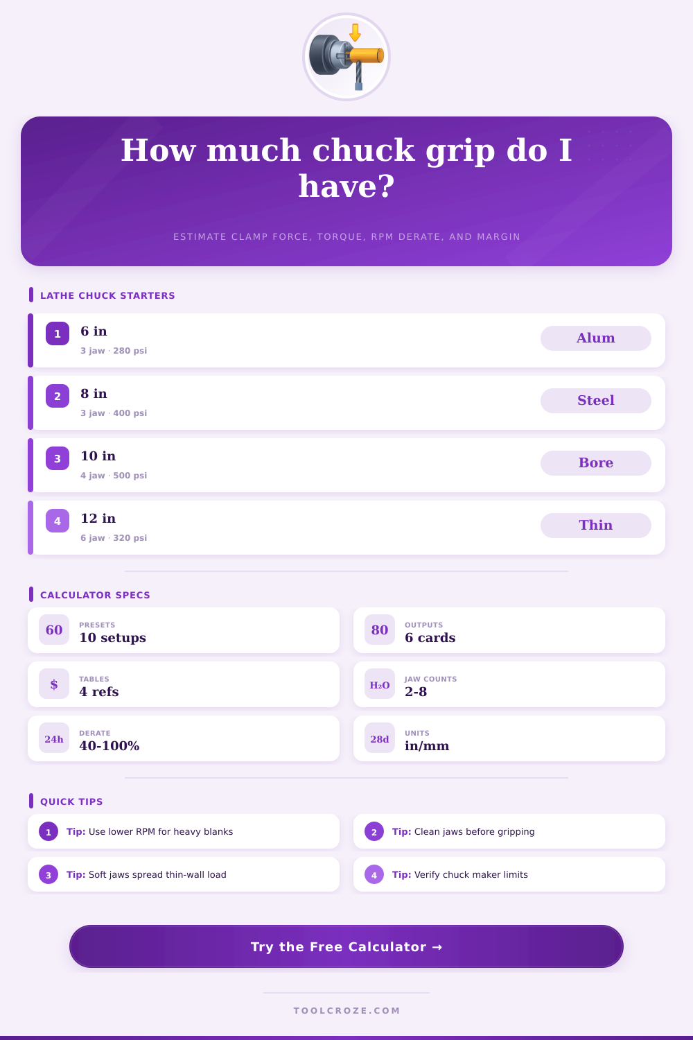
Lathe Chuck Pressure Calculator
Estimate actuator force, total jaw clamping force, holding torque, RPM derate, and safety margin for hydraulic or power chucks.
Choose a starting setup, then adjust pressure, piston area, friction, jaw radius, RPM retention, and safety factor to match the chuck and part.
Calculation breakdown
| Preset | Typical setup | Starting pressure | Derate |
|---|---|---|---|
| 6 in Steel Bar | 3 jaw, 2.25 in mild steel | 360 psi | 85% |
| 8 in Rough Turn | 3 jaw, 4 in alloy stock | 520 psi | 72% |
| 10 in Soft Jaws | Bored jaws, 5.5 in aluminum | 300 psi | 82% |
| 12 in Thin Tube | 6 jaw, 7 in thin-wall tube | 220 psi | 70% |
| Large Bore Clamp | 4 jaw, 9.5 in face grip | 450 psi | 62% |
| Jaw style | Friction start | Best fit | Watch point |
|---|---|---|---|
| Hard serrated jaws | 0.18 to 0.28 | Rough steel, cast iron | Marks finished surfaces |
| Bored soft jaws | 0.10 to 0.16 | Finished diameters | Needs full contact |
| Pie jaws or ring jaws | 0.11 to 0.17 | Thin rings, tubing | Lower point pressure |
| Sleeve pads | 0.14 to 0.22 | Short precision stock | Limited diameter range |
| Aluminum soft pads | 0.08 to 0.13 | Delicate parts | Can embed chips |
| Part material | Dry friction | Light oil | Calculator use |
|---|---|---|---|
| Mild steel | 0.18 to 0.25 | 0.10 to 0.16 | General turning |
| Stainless steel | 0.14 to 0.22 | 0.08 to 0.13 | Use conservative grip |
| Aluminum | 0.12 to 0.20 | 0.08 to 0.12 | Soft jaw contact |
| Cast iron | 0.20 to 0.30 | 0.12 to 0.18 | Dusty dry surfaces |
| Plastic | 0.08 to 0.18 | 0.05 to 0.10 | Low pressure, support |
| RPM retention | Meaning | Typical situation | Action |
|---|---|---|---|
| 90 to 100% | Minimal speed loss | Low RPM, small chuck | Normal checks |
| 75 to 90% | Moderate derate | Common power chuck use | Confirm chart |
| 60 to 75% | High-speed concern | Large jaws or high RPM | Reduce load |
| 40 to 60% | Severe derate | Near speed limit | Slow spindle |
When it comes to lathe parts that become loose, it is the grip between the jaw that is the cause of the looseness, not the lathe itself or the tooling. The torque that is create that prevents the part from spinning is created by the pressure that reaches the chuck actuator (as create through the internal component of the chuck) multiplied by the radius at which the friction between the jaws and the part acts. If a person should miss any of these variable, the margin of safety between properly securing the part and the part flying from the machine decreases.
The calculator can be used to process the math following the entry of parameter like hydraulic pressure, jaw count, friction between the part, and the radius at which the jaws contact the part. Each of these parameter are important to the function of the lathe in that they help to determine the torque value of the setup. For instance, the hydraulic pressure can be entered directly into the calculator, but the area of the piston is not the same than the total area of the cylinder bore; instead, the area of the piston is the area of the bore minus the area of the draw tube (or wedge).
Lathe Chuck Grip and Safety Calculator
The ratio of the chuck multiplies the force create by the actuator to the normal clamp load of the jaws. The friction between the jaws and the part multiplies that normal clamp load into a tangential force, and the radius at which that force is applied can be used to calculate the resulting torque. Each of these parameters have the potential to introduce uncertainty into the calculation; therefore, a safety factor is apply to the calculation at the very end.
One of the most important variable of the calculation that many machinist may not think of is the variable of friction between the part and the jaws. Friction is not a constant, but changes based off the type of material that are used in each of the jaws and the parts themselves. For instance, a serrated hard jaw may have a friction coefficient of 0.20 when clamping into a piece of mild steel, but that same set of jaws may have a friction coefficient of below 0.12 when clamping into a piece of finished stainless steel.
Conversely, softer jaw that are bored to fit the part will have a higher coefficient of friction (due to the much larger area of contact), but the soft jaws may have a lower friction coefficient due to the smoother surface of the softer jaws compared to the serrations on the hard jaw. Additionally, thin wall parts present a different problem to the lathe operator; too much pressure will collapse the thin wall of the part prior to the jaws slipping. Thus, the limit of pressure for thin wall parts is determined not by the torque calculation, but by the strength of the thin wall of the part.
A table of starting friction coefficient is provided on the page to assist the machinist in determining the coefficient of friction between the part and the jaws without guessing at that value. Centrifugal force also introduces another variable into the calculation. For instance, a jaw chuck that retains 85% of its static clamp force at 1,200 rpm may only retain 65% of that static clamp force at 2,800 rpm if the jaws are heavy.
Thus, another variable called derate must be entered into the calculation to account for this lost clamp force of the chucks at high rpm. The margin of safety for a part is even more smaller if that part has a short grip length or an interrupted surface along its length. Another parameter that can be entered into the calculation is a safety factor.
Because each of the parameters for the calculation are not perfect, a safety factor is apply. Safety factor of 2.0 are typically used for heavy, well balanced parts having full length contact with the jaws of the chuck. Safety factors of 3.0 or higher are used for short grip length, parts that are heavy on one end of the part, or parts with an interrupted contact surface with the chuck jaws.
This safety factor is applied after the derate factor of the chuck; centrifugal force occur prior to the safety factor. The resulting torque that is calculated through the application of these factor is the maximum usable torque of the setup. While many experienced machinist may not need to calculate these number for each workpiece, the calculations can be used for workpieces outside the experience of the operator.
For instance, the experienced machinist may have an instinctive feel for the amount of pressure that is safe to apply to the jaws of the chuck with various materials. For workpieces that are outside the experience of the operator, however, it is important to use these calculations as a starting point; the actual parameter can be adjusted after the first few cuts of the workpiece. Finally, calculations are a means of an end; they should never supersede the pressure and speed chart created by the chuck’s manufacturer.
These charts account for the strength of the draw tube, the wedge angle of the chuck jaws, and the mass of the jaws. The calculator allow the machinist to understand where their calculation lie in relation to these published limits; thus, providing the machinist with an understanding of their position relative to the manufacturer’s limit before initiating the rotation of the chuck and workpiece. You should of used these charts to avoid errors.
It is important to recieve accurate data for the most moddern machines. If you cant get the right data, the calculations will be wrong. Dont forget that the jaws length also matter.
Use teh calculator with care. It is a lot of work to do it manualy.