Orbital Sander Air Consumption Calculator
Estimate continuous SCFM demand, total sanding air volume, compressor reserve, tank-only runtime, and hose pressure loss for pneumatic orbital and dual-action sanders.
⚙Real Sander Presets
Choose a common shop or bodywork setup, then adjust the rated SCFM, trigger time, compressor delivery, and air line details to match your equipment.
📏Air Demand Inputs
Air Consumption Results
📊Sanding Pad, Grit, and Material Comparison
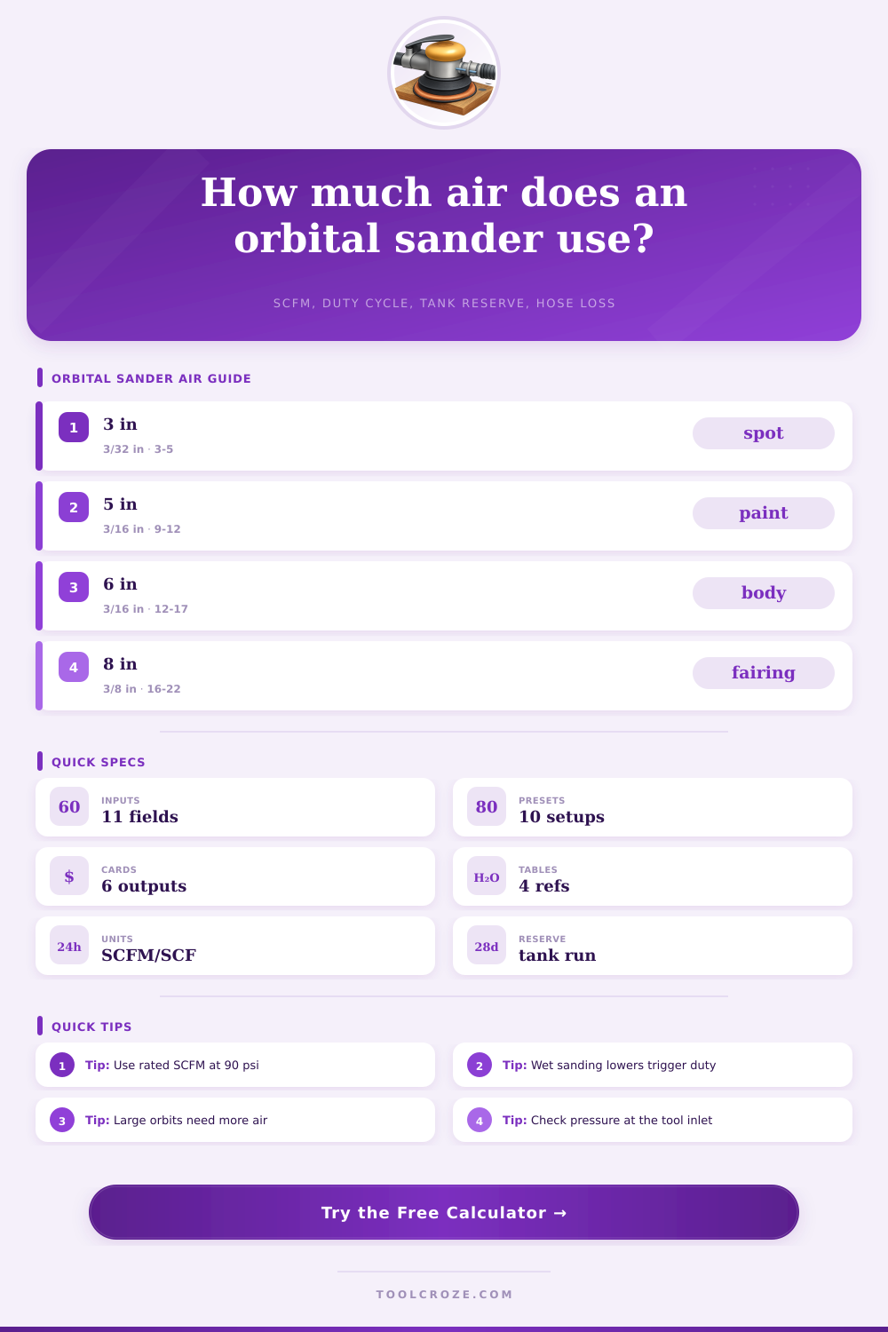
🔧Orbital Sander SCFM Reference
| Sander class | Pad and orbit | Typical rated air | Normal pressure | Planning note |
|---|---|---|---|---|
| Mini random orbital | 2 to 3 in pad, 3/32 to 1/8 in orbit | 2.5 to 5.0 SCFM | 90 psi at inlet | Spot repairs and tight panels |
| Finish palm orbital | 5 in pad, 3/32 to 1/8 in orbit | 6.0 to 10.0 SCFM | 80 to 90 psi | Lower material load, longer finish sessions |
| General DA sander | 6 in pad, 3/16 in orbit | 10.0 to 15.0 SCFM | 90 psi at trigger | Most bodywork and paint prep estimates start here |
| Vacuum DA sander | 6 in pad, 3/16 in orbit, vacuum port | 12.0 to 17.0 SCFM | 90 psi at inlet | Extra airflow supports dust extraction turbine |
| Gear-driven orbital | 5 to 6 in pad, 1/4 in orbit | 14.0 to 20.0 SCFM | 90 psi at inlet | Heavy cut load and stall resistance raise air use |
| Orbital fairing board | 8 in or long board, 3/8 in orbit | 16.0 to 24.0 SCFM | 90 psi at inlet | Often needs large tank and 3/8 in minimum hose |
📝Material Load and Duty Reference
| Material task | Common grit | Load factor | Typical trigger duty | Air planning note |
|---|---|---|---|---|
| Bare hardwood or softwood | 120 to 220 | 0.96 | 55% to 75% | Frequent inspection keeps duty moderate |
| Paint removal | 40 to 80 | 1.12 | 70% to 90% | Coarse discs and pressure increase vane load |
| Automotive primer or filler | 80 to 180 | 1.08 | 65% to 85% | Bodywork uses long trigger-on passes |
| Clear coat color sanding | 800 to 2000 | 0.88 | 45% to 65% | Wet work and cleaning breaks reduce average air |
| Fiberglass gelcoat | 80 to 320 | 1.10 | 65% to 85% | Dust extraction and larger pads are common |
| Aluminum sheet prep | 120 to 320 | 1.02 | 55% to 75% | Use lighter pressure to limit heat and loading |
| Solid surface countertop | 180 to 400 | 1.04 | 60% to 80% | Even finish passes need stable pressure |
| Drywall compound | 180 to 220 | 0.82 | 35% to 55% | Low pressure and vacuum control reduce consumption |
🧪Hose and Compressor Planning Table
| Calculated flow | Preferred hose ID | Receiver tank range | Compressor target | Use case |
|---|---|---|---|---|
| Up to 5 SCFM | 1/4 in short whip | 10 to 20 gal | Flow plus 15% | Mini spot sanding and polish prep |
| 5 to 10 SCFM | 5/16 or 3/8 in | 20 to 30 gal | Flow plus 20% | 5 inch finish orbital work |
| 10 to 15 SCFM | 3/8 in | 30 to 60 gal | Flow plus 25% | Single 6 inch DA bodywork |
| 15 to 22 SCFM | 3/8 or 1/2 in | 60 to 80 gal | Flow plus 30% | Vacuum DA or gear-driven removal |
| 22+ SCFM | 1/2 in main, 3/8 in whip | 80+ gal | Continuous duty system | Multiple sanders or fairing boards |
📋Pad, Orbit, and Grit Match Grid
| Pad and orbit | Best grit range | Material fit | Air draw tendency | Finish tradeoff |
|---|---|---|---|---|
| 3 in, 3/32 in orbit | 320 to 1500 | Clear coat nibs, small primer spots | Low | Fine control, slow coverage |
| 5 in, 1/8 in orbit | 120 to 320 | Wood, solid surface, finish prep | Moderate | Smoother scratch pattern |
| 6 in, 3/16 in orbit | 80 to 220 | Primer, filler, paint edge feathering | High | Good balance of cut and finish |
| 6 in, 1/4 in orbit | 40 to 120 | Paint stripping and rough leveling | Very high | Fast removal, coarser swirl risk |
| 8 in, 3/8 in orbit | 40 to 120 | Fiberglass and fairing compound | Very high | Flat coverage, large compressor demand |
💡Practical Air Planning Tips
When you set up a pneumatic orbital sander, you need to have an understanding of how the pneumatic orbital sander utilize air in order to make sure that the pneumatic orbital sander will work correctly. The pneumatic orbital sander will have a peak flow rate in Standard Cubic Feet per Minute (SCFM). This SCFM will represent the flow rate of air from the pneumatic orbital sander when the trigger is pull, and the air compressor is set to ninety psi.
Because the flow rate of air will be less in actual operation of the pneumatic orbital sander, you cant rely upon the SCFM flow rate of air as a measurement of how much air the pneumatic orbital sander will use during operation. Another factor to consider is the duty cycles of the pneumatic orbital sander. The duty cycle represents the percentage of time that the trigger of the pneumatic orbital sander is held in the depressed position.
Air needs of a pneumatic orbital sander
For instance, during spot repairs with the pneumatic orbital sander, the pneumatic orbital sander will need to be frequent stopped in order to inspect the work. Similarly, when working on an area of the object being repaired, the work will be performed in more longer continuous periods without stopping the pneumatic orbital sander. Thus, the percentage of time that the trigger is depressed will affect the air demand of the pneumatic orbital sander.
Another factor in the air system of the pneumatic orbital sander is the size of the hoses that is used to connect the air compressor to the pneumatic orbital sander. Air will naturaly lose some of its pressure as it passes through a hose of a certain size. For instance, if the air hoses that are of a fifty foot quarter-inch in diameter is used to connect the air compressor and the pneumatic orbital sander, the air will lose some of its pressure before it reaches the pneumatic orbital sander.
The loss of pressure to the pneumatic orbital sander will cause the motor to turn at a slow rate, and make the orbital movement of the pneumatic orbital sander feel sluggishly. To avoid this loss of air pressure, you can use hoses of a larger diameter (for instance, a three eighths inch hose), or the length of the hose can be shorten. The size of the air compressor tank will also factor into the air system of the pneumatic orbital sander.
For instance, if the air compressor cannot provide enough air to the pneumatic orbital sander at the rate that the pneumatic orbital sander consume air, then the air tank will help to supply the pneumatic orbital sander while the compressor refills the tank with compressed air. However, if two pneumatic orbital sander are in use at the same time, the air tank will empty at a faster rate. Additionally, when the air tank becomes empty of compressed air, the air compressor will have to cycle to refill the tank with compressed air.
The air requirement of the pneumatic orbital sander may also be affected by the material that is being sanded, and the grit of the sanding discs. If you use coarse grit sanding discs on bare metal or fiberglass substrates, the air compressor will have to work harder to provide the air necessary to overcome the resistance of the material being sanded, relative to the air required when using fine grit sanding discs on a smooth primer substrate. Additionally, if the material is being wet sanded, the air demand will be reduced due to the need to periodically lift the pneumatic orbital sander to remove the slurry from the material being sanded.
Finally, it is important to ensure that the air compressor has a sufficient compressor margin in relation to the air demand of the pneumatic orbital sander. The compressor margin represent the amount of surplus air that the air compressor can produce relative to the air demand of the pneumatic orbital sander. A surplus of ten or fifteen percent in the air capacity of the air compressor will ensure that the air compressor has time to recover after providing air to the pneumatic orbital sander.
If the air compressor is required to run at the exact limit of the air demand of the pneumatic orbital sander, the air tank will sag in pressure, and the pneumatic orbital sander will not be able to operate at its potential. Thus, you should of sized the air compressor according to the air demand rate of the pneumatic orbital sander when it is continuously in operation.