Cut Off Tool Air Consumption Calculator
Estimate trigger-on SCFM, average compressor load, air used per hour, hose pressure drop, tank reserve, and cut time for pneumatic abrasive cut-off tools.
⚙ Real Cut-Off Tool Presets
Choose a shop scenario, then adjust pressure, hose, tank, and cutting details to match your setup.
🔧 Air, Wheel, Hose, and Cut Inputs
Calculation Breakdown
📊 Current Setup Snapshot
📐 Abrasive Wheel and Tool Spec Comparison
| Wheel and Tool Setup | Typical Max RPM | Air Demand Range | Best Fit |
|---|---|---|---|
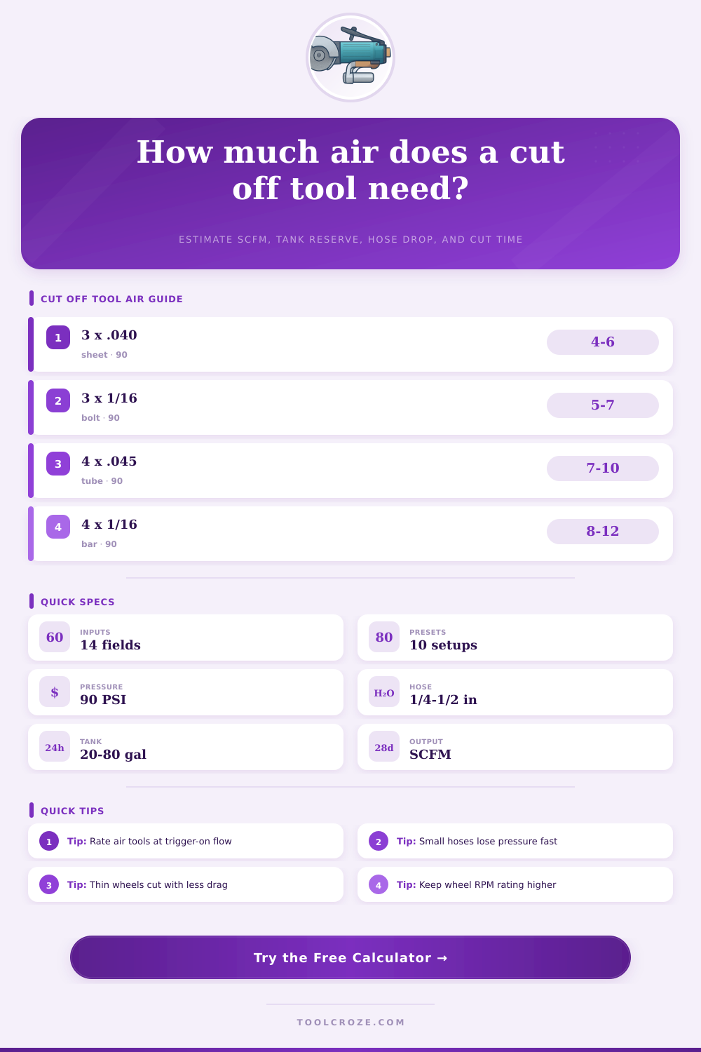
| 2.5 in x .035 in compact cut-off wheel | 25,000-30,000 RPM | 3.5-5.0 SCFM at 90 PSI | Thin duct sheet, clips, tight access slots |
| 3 in x .040 in general cut-off wheel | 20,000-25,000 RPM | 4.5-6.5 SCFM at 90 PSI | Auto sheet, exhaust clamps, small bolts |
| 3 in x 1/16 in reinforced wheel | 18,000-22,000 RPM | 5.5-7.5 SCFM at 90 PSI | Threaded rod, hardware trimming, rougher cuts |
| 4 in x .045 in high-speed cut-off wheel | 15,000-19,000 RPM | 7.0-10.0 SCFM at 90 PSI | Tubing, brackets, longer mild steel cuts |
| 4 in x 1/16 in heavy cut-off wheel | 13,500-15,300 RPM | 8.0-12.0 SCFM at 90 PSI | Bar stock, cast tabs, cuts with side clearance |
⚒ Material Cutting Reference
| Material | Air Load Factor | Starting Cut Rate | Wheel Note |
|---|---|---|---|
| Thin auto or duct sheet | 0.88 | 0.28 in²/min | Use thin .035-.040 in wheels to reduce heat and air draw. |
| Mild steel tube or sheet | 1.00 | 0.20 in²/min | General reinforced aluminum-oxide wheels are the baseline. |
| Stainless steel | 1.18 | 0.13 in²/min | Use light pressure and avoid glazing the wheel. |
| Aluminum | 0.92 | 0.24 in²/min | Use a wheel rated for non-ferrous metal to reduce loading. |
| Cast iron | 1.12 | 0.16 in²/min | Expect dust and slower starts on thick edges. |
| Hardened bolt or rod | 1.22 | 0.11 in²/min | Use a reinforced wheel and short pauses to manage heat. |
💨 Hose Pressure Drop Reference
| Hose ID | Good For | Approx. Drop at 20 SCFM / 50 ft | Cut-Off Tool Guidance |
|---|---|---|---|
| 1/4 in | Short light tools | About 6.0 PSI | Works for compact 2.5-3 in tools only when the run is short. |
| 5/16 in | Mobile trim work | About 3.2 PSI | Acceptable for intermittent 3 in cutting with high-flow couplers. |
| 3/8 in | General shop use | About 1.8 PSI | Preferred baseline for 3-4 in pneumatic cut-off tools. |
| 1/2 in | High-flow stations | About 0.6 PSI | Best for long runs, 4 in wheels, and high duty cycles. |
📋 Compressor Planning Table
| Shop Pattern | Typical Trigger Time | Useful Compressor Range | Tank Note |
|---|---|---|---|
| Occasional panel cuts | 3-8 min/hr | 4-6 SCFM at 90 PSI | 20-30 gal can work if recovery pauses are acceptable. |
| Exhaust or bracket fabrication | 8-16 min/hr | 6-10 SCFM at 90 PSI | 30-60 gal improves recovery during repeated cuts. |
| Batch rod and hardware trimming | 15-25 min/hr | 9-14 SCFM at 90 PSI | Use a larger receiver or expect pressure cycling. |
| Near-continuous cut-off station | 25-40 min/hr | 12-18 SCFM at 90 PSI | Compressor delivered SCFM matters more than tank size. |
💡 Practical Calculation Tips
A pneumatic cut-off tool require a consistent supply of compressed air to perform correctly. The pneumatic cut-off tool will perform poorly if the compressor cannot provides enough air for the pneumatic cut-off tool. Many shops will find themselves in a situation where the pneumatic cut-off tool lose power while performing a cut because the compressor cannot provide enough air for the pneumatic cut-off tool.
The air demand for a pneumatic cut-off tool is not a fixed number; rather, the demand for air change based on the size of the cutting tool’s wheel, the hardness of the material being cut, the length of the air hose connect to the pneumatic cut-off tool, and for how long the user holds the trigger to the pneumatic cut-off tool. Inputs into the calculator will ask the user about the rated flow of the pneumatic cut-off tool. However, the rated flow will not necessarily be the same as the air pressure that reach the pneumatic cut-off tool.
How to check air needs of an air-powered cut-off tool
The regulator settings of the pneumatic cut-off tool, the length of the air hose, and leaks in the coupler that connect the pneumatic cut-off tool to the compressor will lose the air pressure. Additionally, the material that is being cut will increase the air demand of the pneumatic cut-off tool. Materials like stainless steel will create more resistance against the wheel of the pneumatic cut-off tool.
As a result, the air motor of the pneumatic cut-off tool will have to work harder to create the cuts, which will result in the pneumatic cut-off tool using up more air. The air consumption of the pneumatic cut-off tool is another calculation that go into determining the air demand for the pneumatic cut-off tool. The user will be asked to input the length of the cut, the thickness of the material, the approach time to the material, and the number of cuts that will be made per hour.
The air consumption of the pneumatic cut-off tool will allow the calculator to provide a duty cycle for the pneumatic cut-off tool so that the user can understand the true demand for air by the tool rather than use an estimation of that demand. Another factor in the calculation of the demand for air by the pneumatic cut-off tool is the hose pressure drop. If a user utilizes a small air hose to supply air to the pneumatic cut-off tool, such as using a 1/4-inch air hose, the air pressure will drop significant over long distances.
As a result, the pneumatic cut-off tool will have to hold the trigger for longer to perform its cutting operation. This increased holding of the trigger will result in the pneumatic cut-off tool using up more air then if it were supplied through a larger air hose. Reducing the hose pressure drop can be accomplished by utilizing a larger air hose; using a 3/8-inch air hose instead of a 1/4-inch air hose will reduce the drop in air pressure.
The calculation of the tank reserve allows the user to understand how much air is stored in the compressor tank for the pneumatic cut-off tool. If a compressor has a large tank, it can supply air for short period to the pneumatic cut-off tool. However, the large tank will not help the pneumatic cut-off tool if the compressor that supply the air to the tank is too small to meet the demands of the pneumatic cut-off tool.
This calculation will allow the user to understand whether there compressor margin is positive or negative. If the margin is positive, it means the compressor will be able to refill the air tank between cuts by the pneumatic cut-off tool. However, if the margin is negative, it means the compressor is not able to refill the pneumatic cut-off tool’s air tank quick enough for the tank to hold enough air for the pneumatic cut-off tool to perform its tasks.
If a shop desires to add additional pneumatic cut-off tool station, the demand for air will increase. Adding a second pneumatic cut-off station will increase the average demand for air by the shop, but it will not increase the output of the existing compressor. Using this calculator, a shop can decide how many additional stations will have an impact on the shop’s existing compressor before purchasing additional pneumatic cut-off tool station.
The calculator allow a shop to test different variables within the pneumatic cut-off tool to determine what the best configuration of pneumatic cut-off tools will be for that shop. By using the calculator, the shop will no longer have to guess if their existing compressor is sufficient for the air demands of the pneumatic cut-off tools that the shops crew will assign to the shop.