Gasket Compression Calculator
Estimate gasket compression, seating stress, retained clamp after flange pressure, material recovery gap, and bolt torque from thickness, area, preload, pressure, and joint hardware.
Pick a common flange or cover scenario, then adjust the measured thickness, area, preload, and pressure values for your actual joint.
Formula Breakdown
| Gasket family | Typical seating stress | Compression band | Recovery guide | Common use |
|---|---|---|---|---|
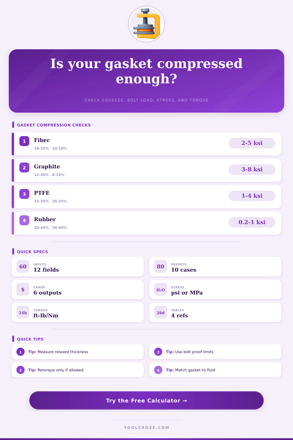
| Compressed fiber sheet | 2,000-5,000 psi / 14-34 MPa | 10-25% | 10-18% | Water, oil, general flanges |
| Flexible graphite sheet | 3,000-8,000 psi / 21-55 MPa | 12-30% | 8-15% | Steam, heat, chemical duty |
| PTFE envelope or filled PTFE | 1,500-4,000 psi / 10-28 MPa | 15-35% | 20-35% | Chemical resistance, low friction |
| Spiral wound graphite filler | 5,000-10,000 psi / 34-69 MPa | 15-30% | 8-15% | ASME pipe flanges, process service |
| NBR rubber sheet | 200-1,000 psi / 1.4-6.9 MPa | 20-40% | 35-60% | Pump covers, low pressure oil |
| Silicone sanitary gasket | 150-800 psi / 1.0-5.5 MPa | 20-35% | 30-55% | Tri-clamp, sanitary closures |
| Cork rubber cover gasket | 150-700 psi / 1.0-4.8 MPa | 15-35% | 25-45% | Gearboxes and stamped covers |
| Metal jacketed gasket | 8,000-15,000 psi / 55-103 MPa | 5-15% | 3-8% | Exhaust, heat exchangers, hard flanges |
| Compression result | Typical meaning | Likely issue | Next check |
|---|---|---|---|
| Below material minimum | Under-seated gasket | Weeping, low surface stress | Check bolt load and flange flatness |
| Within target band | Practical installed squeeze | Normal verification needed | Confirm retained stress after pressure |
| Above material maximum | Over-compressed gasket | Crushing, creep, extrusion risk | Review thickness and compression stops |
| High recovery, low stress | Soft gasket rebound available | May relax under heat or aging | Check retorque rules and material data |
| Low recovery, high stress | Hard or metal gasket behavior | Needs smooth, rigid flange faces | Confirm finish, flatness, and bolt proof |
| Check | Formula used | Good sign | Caution sign |
|---|---|---|---|
| Seating stress | Total bolt load / gasket area | At or above material target | Below minimum seating stress |
| Opening force | Flange pressure x gasket area | Small versus clamp load | Pressure force consumes clamp |
| Retained clamp | Adjusted clamp - opening force | Positive with stress margin | Zero or negative retained load |
| Torque estimate | T = K x F x d | Below bolt and flange limits | Above hardware rating or galling risk |
| Recovery gap | Thickness loss x recovery percent | Enough rebound for small relaxation | Very low recovery in cyclic service |
| Nut factor K | Condition | Torque impact | Use note |
|---|---|---|---|
| 0.12-0.16 | Well lubricated threads and nut face | Lower torque for same preload | Verify lubricant is approved for service |
| 0.18-0.22 | Typical light oil or general shop estimate | Middle planning range | Good default when no test data exists |
| 0.23-0.30 | Dry, rough, plated, or inconsistent threads | Higher torque and more scatter | Use caution with galling and proof load |
| Measured K | Load cell or calibrated fastener trial | Best preload estimate | Use project-specific data when critical |
Gasket compression are essential to understanding bolted joints. The compression of the gasket and the change in thickness of the gasket are both critical to determining whether the gasket will provide a seal or allow for fluid to leak from the joint. If the change in thickness of the gasket isnt sufficient, then the stress on the joint will be too low to prevent fluid from traveling through the joint.
However, if the change in thickness of the gasket is too great, then the fibers in the gasket will be crushed, and the gasket wont be able to maintain its seal. In order to calculate the gasket compression, a variety of different measurements of the joint are required. The initial thickness of the gasket is the thickness of the gasket prior to the application of load.
Gasket Compression and Sealing in Bolted Joints
The compressed thickness of the gasket is the thickness of the gasket after the application of load. The effective area of the joint is the area of the ring segment that is responsible for the clamp load, not the total area of the flange face. The number of bolt and the preload on each bolt determine the total clamp load that can be applied to the joint.
However, the pressure created by fluids within the joint will work in the opposite direction to compress the joint. The nut factor and the diameter of the bolt allow the calculation of the preload on each bolt from the specified torque that must be applied to the bolt when a wrench tightens it. These different parameters can be used to calculate the seating stress of the gasket, the retained stress of the bolt after the fluid pressure is applied to the joint, and the amount of material recovery of the gasket.
The material of the gasket can change the load required to compress the gasket. For example, if the gasket is made of compressed fiber sheets, then the squeeze and recovery of the gasket sheets must be moderate to allow the sheets to accommodate for the loads created by the fluid within the joint. However, if the joint is made of flexible graphite sheets, then these sheets can withstand high levels of stress and temperatures but require a higher degree of squeeze to maintain the seal between the joint faces.
Additionally, if the gasket is made of PTFE material, it will easily compress and recover from deformation but may creep in the application of a constant load to the joint, so a calculation of the retained stress of the PTFE is necesary. Gaskets that are made of rubber compounds are soft to allow the gasket to conform to the flange face; however, if the load is too high or the flange faces isnt even with one another, the rubber compounds will extrude from the joint. A calculator can help to switch between these different material families to ensure that the joint stress and gasket compression band match the requirements of the selected gasket material.
The geometry of the flanges can also impact the gaskets compression. For example, raised faces apply the clamp load to a small ring area of the flange face. The area of the tongue and groove joint reduces the surface area of the joint that is exposed to the clamp load.
In joints that are subjected to cyclic thermal loads, the flange faces may expand and contract, and the load on the gasket is relieved, so the allowance of material recovery must be considered. Finally, for low-pressure or vacuum joints, the required clamp load is lower but must still be sufficient to ensure that the gasket remains in contact with the flange faces despite flange distortion caused by fluid pressure. The use of a wrench to tighten the bolts will require the calculation of the torque that is required to achieve the preload on each bolt.
This calculation will use the per-bolt load divided by the nut factor to determine the torque value that should be applied to each bolt. The use of different tightening patterns can create scatter in the load application. The calculation cannot determine the need for retightening the bolts.
However, it can determine the margin of load that can be applied to the bolts if the flanges are to be retightened. The measurement of recovery is the amount the gasket material returns to its original thickness after the gasket is compressed. Some of the change in thickness of the gasket is elastic, and the material returns to its original thickness after the application of the clamp load on the joint.
Materials that have a higher recovery value will allow for a small error in the initial compression of the gasket. The recovery gap is the product of the change in thickness of the gasket that is compressed by the clamp load times the percentage of recovery of the gasket material. This value is the estimate of the spring that the gasket material will exhibit after being compressed.
Some of the mistakes in calculating joint load will be to use the wrong area of the flange or to fail to account for the internal pressure within the joint. For example, the area of the flange face that is used in the calculation can be the entire flange face or the effective area of the joint that is loaded by the clamp load. If the entire flange face is used in the calculation, the seating stress may appear to be sufficient to create the seal between the flanges.
However, the internal pressure will act on the same area to create an opposing force, and the joint may fail to remain sealed once it is pressurized to its internal pressure. A retained stress check will reveal whether such a joint will remain sealed under its operational pressure. The condition of the flanges and the methods of tightening the bolts are outside the calculations.
A warped or pitted area of the flange will not generate the same clamp load on the gasket material that can be calculated for a flat flange face. The use of a star pattern to tighten the bolts with multiple passes with the wrench will allow for the even distribution of the clamp load on the joint. The use of a star pattern for the tightening of the bolts will be more effective than changing the nut factor.
The calculation of the loads on the flanges and the bolts cant tell the technician if the retightening of the bolts is necessary. However, if the technician decides to retighten the bolts, the calculation could of provided the margin of load that should be applied to each bolt. The calculation of each of these parameters allows the technician to understand the performance of the bolts and the gasket.
Each of the parameters is interrelated to the others. For instance, if one load is changed, the other loads change to reflect this change in load. If each of the loads and stresses within the joint are within the limits of the materials, the joint will remain within the limits of those materials.
If the calculations of the joint loads fail, the calculation will indicate which parameter must be adjusted before the bolts are tightened.