O Ring Groove Calculator
Size radial and face seal glands by checking squeeze, volume fill, O-ring stretch, groove diameters, side clearance, and extrusion clearance before the groove is cut.
Choose a named starting point, then adjust dimensions to match the actual gland standard, elastomer, finish, and pressure requirement.
Calculated gland check
| Seal type | Typical squeeze | Typical fill | Stretch or compression target | Workshop note |
|---|---|---|---|---|
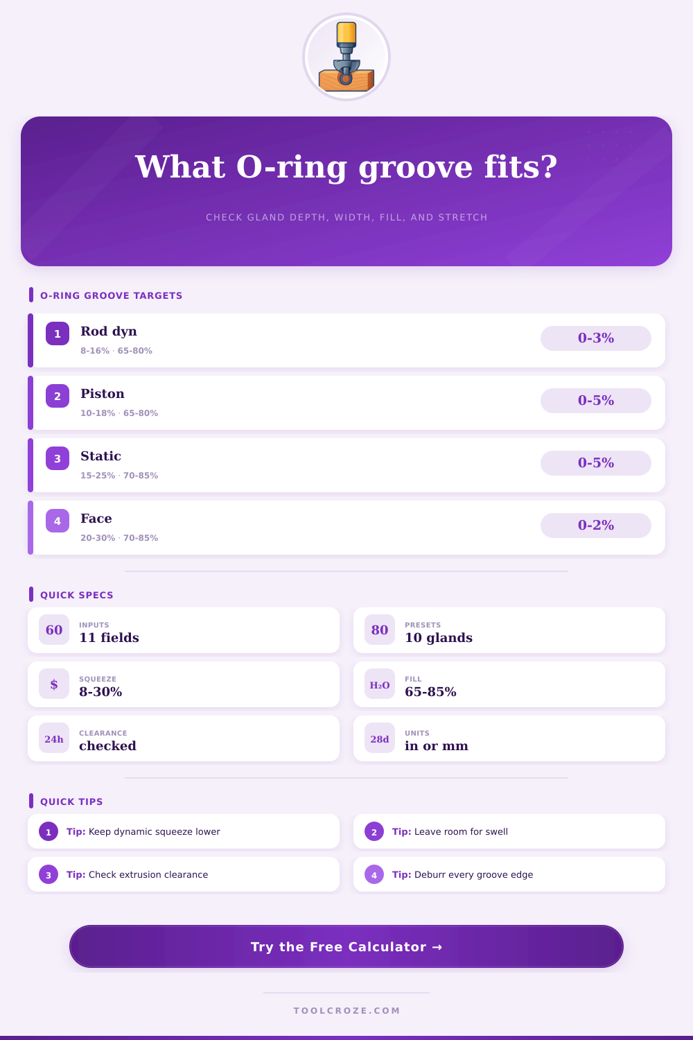
| Rod dynamic radial | 8% to 16% | 65% to 80% | 0% to 3% stretch | Use lower squeeze to limit friction and heat. |
| Piston dynamic radial | 10% to 18% | 65% to 80% | 0% to 5% stretch | Check bore finish and pressure direction. |
| Static radial | 15% to 25% | 70% to 85% | 0% to 5% stretch | Higher squeeze is acceptable when motion is absent. |
| Face seal | 20% to 30% | 70% to 85% | 0% to 2% stretch or slight compression | Leave radial space for pressure energizing. |
| Nominal CS | Metric equivalent | Dynamic depth range | Static depth range | Common width range |
|---|---|---|---|---|
| 0.070 in | 1.78 mm | 0.059 to 0.064 in | 0.052 to 0.060 in | 0.095 to 0.110 in |
| 0.103 in | 2.62 mm | 0.086 to 0.095 in | 0.077 to 0.088 in | 0.140 to 0.160 in |
| 0.139 in | 3.53 mm | 0.116 to 0.128 in | 0.104 to 0.118 in | 0.185 to 0.215 in |
| 0.210 in | 5.33 mm | 0.176 to 0.193 in | 0.158 to 0.179 in | 0.285 to 0.330 in |
| 0.275 in | 6.99 mm | 0.231 to 0.253 in | 0.206 to 0.234 in | 0.375 to 0.430 in |
| O-ring hardness | Up to 500 psi | 500 to 1500 psi | 1500 to 3000 psi | Backup ring cue |
|---|---|---|---|---|
| 70A | 0.006 in gap | 0.003 in gap | Use backup | Consider backup above moderate pressure. |
| 75A | 0.007 in gap | 0.004 in gap | 0.002 in gap | Good general hydraulic choice. |
| 80A | 0.009 in gap | 0.005 in gap | 0.003 in gap | Better extrusion resistance. |
| 90A | 0.012 in gap | 0.007 in gap | 0.004 in gap | Often paired with higher squeeze force. |
| Feature | Typical target | Why it matters | Calculator check |
|---|---|---|---|
| Gland depth | CS minus squeeze | Controls sealing load and friction. | Actual squeeze card |
| Groove width | O-ring area divided by fill | Leaves room for swell and tolerance stackup. | Volume fill card |
| Corner radius | Small, smooth radius | Sharp corners can cut the elastomer. | Safety note |
| Side clearance | Positive clearance | Prevents axial pinching in the gland. | Spec grid |
| Diametral clearance | Pressure dependent | Large gaps allow extrusion under pressure. | Clearance card |
An O-ring groove is a critical component of an assembly that uses O-rings. The O-ring groove determine how the O-ring will seal and how the O-ring will perform under the operating pressure. Many people may believe that the O-ring is responsible for all of the sealing works that it performs.
However, it is the O-ring groove that creates the squeeze, the clearance, and a space for the O-ring to expand. If the dimensions of the groove are incorrect, the O-ring will extrude, the O-ring will pinch, or the O-ring will not properly energize. Because changes to the dimensions of the groove can cause the O-ring to fail, the dimensions of the groove must be precisely.
How O-ring Grooves Affect Seals
One of the primary variable that must be considered in the design of the groove is the squeeze. The squeeze is the percentage of the cross section of the O-ring that is compressed when the assembly is closed. If there is too little squeeze, there will not be enough force applied to the O-ring to prevent the fluid from passing through the seal.
If there is too much squeeze, the elastomer may overheat due to the friction created between the seal components, or it may be difficult to assemble the components due to the required compressive force. Dynamic rod seals will require a modest squeeze to allow the O-ring to run cool. Static face seals will allow for more squeeze because there is no sliding motion between the two component.
A calculator can be used to determine the squeeze if the cross section of the O-ring and the gland depth are known. Another limitation that must be considered in the design of the groove is the volume fill. The O-ring must have enough space to sit in the groove, and there must be additional space for the O-ring to swell due to heat or the fluids that it encounters.
If the O-ring swell, it can lead to a hydraulic lock if the gland was sized for the cool O-ring only. This swell allowance must be considered in the calculations of the volume fill. If the volume fill parameter returns a high value, the groove must be widened to allow for the O-ring to properly sit in the groove.
The depth of the groove will control the squeeze of the O-ring. Another consideration is the stretch that the O-ring will experience when changing the diameter of the O-ring to place it into its installed position. If the O-ring is being installed on a piston, the piston seal will stretch.
If the O-ring is being installed on a rod, the rod seal will compress. A calculator can report the amount of stretch that is experienced by the O-ring to ensure that there is no excessive stretch of the O-ring. Excessive stretch will thin the cross section of the O-ring and the O-ring land that seal the components.
Another factor to consider is the clearance between the O-ring and the component. The pressure that is applied to the O-ring will force the O-ring to follow the path of least resistance. This might be into the gap between the moving parts.
The harder the compound and the smaller the gap, the more resistance will the O-ring put up. There will be a limit to this resistance. As the pressure increases, the allowable gap for the O-ring to move decreases.
This means that backup rings may be required. The diametral clearance of the components can be checked against these limits to ensure that backup rings are required or not. The real part that are manufactured will never match the nominal dimensions of the drawing.
The surface finish of the groove will impact the performance of the O-ring and the corner radii of the groove will impact how the O-ring is installed into the component. Sharp corners may cut the O-ring and rough bores may abrade the O-ring during every cycle that the component performs its function. While a calculator will not measure the surface finish or corner radii of the components, the calculator will require the consideration of these dimensions as the depth and width of the groove will assume that the grooves has clean edges.
Another consideration is how the temperature changes will impact the O-ring and it’s groove. Because elastomers expand and contract differently than the metals used in the components, the swell that is allowed for the O-ring is only an estimate. Furthermore, the fluid used in the component changes the volume of the O-ring over time.
For these reasons, O-ring builders will typically allow a higher swell percentage than the one that is indicated on the elastomer datasheet. Using a higher percentage for swell allowance during machining the components will prevent trouble shooting the O-ring groove once the assembly is completed. The assembly sequence for the components can impact the O-ring.
If the O-ring must pass over threads or other ports during assembly, it can be nicked. In these instances, a cone or a sleeve can be used to protect the O-ring during installation. However, those who only consider the final assembled component from the drawing may skip these steps.
A calculator will provide the correct squeeze and volume fill numbers for the O-ring, but it cannot warn of any damage to the O-ring during assembly. The assembled component with the groove for the O-ring must be tested. Even if the static cover will create the proper squeeze for the static seal, a moving rod at a specific temperature may require a different squeeze or compound to allow even operation.
Furthermore, a calculator will provide the proper numbers to the designer, but the O-ring may need to be tweaked to account for the actual operation of the component. By keeping notes of what works during test assemblies, the designer will have better data to work with in future components. Every dimension within the groove of the O-ring is important because every dimension impact the function of the O-ring.