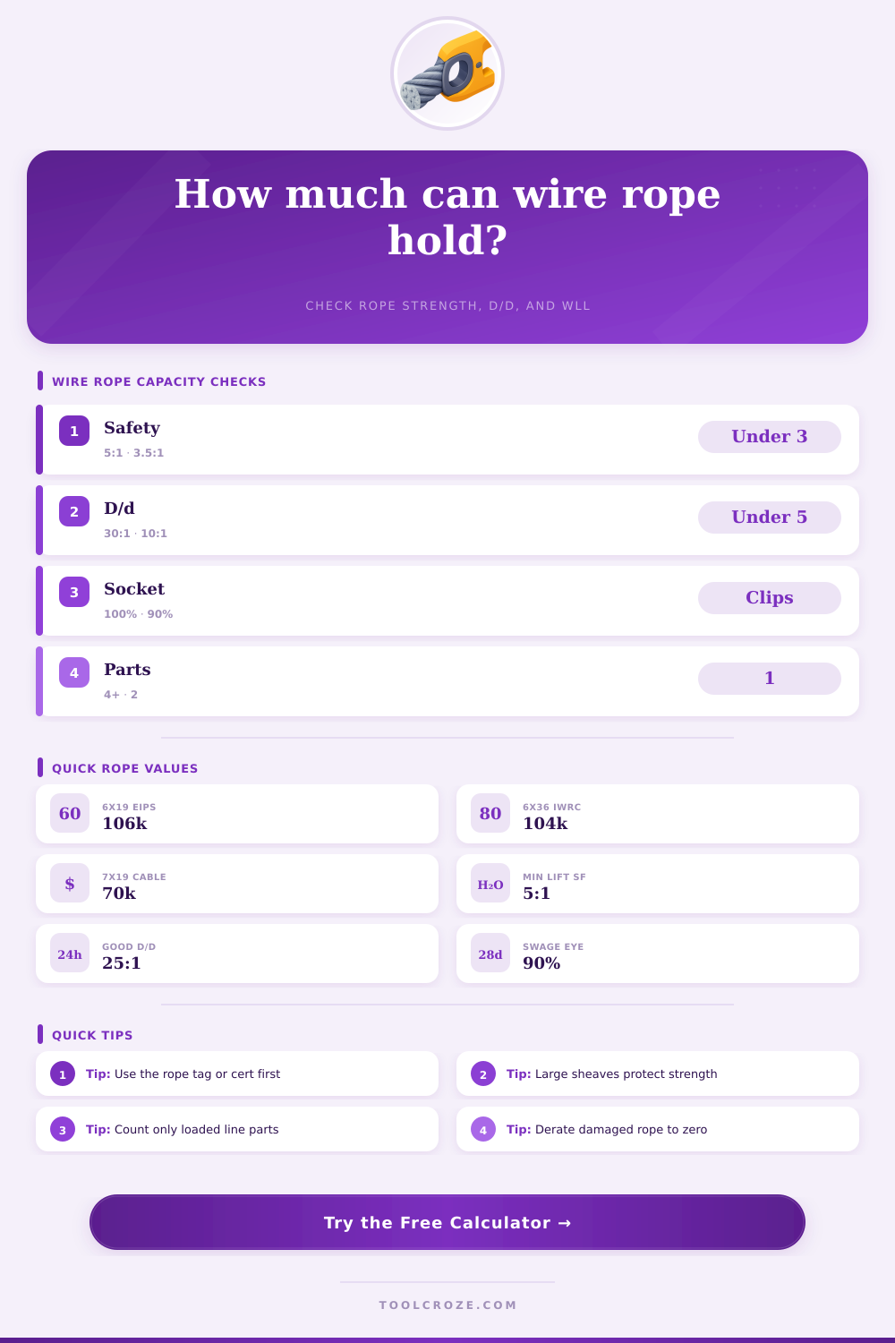
Wire Rope Capacity Calculator
Estimate minimum breaking strength and working load limit from rope diameter, construction, grade, strength factor, safety factor, number of parts, sheave D/d ratio, bend efficiency, and termination efficiency.
⚙Real Wire Rope Presets
📏Rope And System Inputs
🧱Rope Construction / Spec Grid
📊Breaking Strength Factor Reference
| Rope type | Typical factor | Use in formula | Planning note |
|---|---|---|---|
| 6x19 or 6x25 IWRC EIPS | 106,000 lb/in² | General hoist and rigging estimate | Use certified MBS when available |
| 6x36 IWRC EIPS | 104,000 lb/in² | Flexible crane and boom hoist rope | Good bending service with proper sheaves |
| 6x19 fiber core EIPS | 94,000 lb/in² | Flexible lower-strength estimate | Less crush resistant than IWRC |
| 7x19 galvanized aircraft cable | 70,000 lb/in² | Controls, guards, light winch lines | Not automatically a lifting sling |
| Stainless 7x19 cable | 58,000 lb/in² | Corrosion-resistant cable estimate | Lower MBS than carbon steel cable |
📐D/d Bend Efficiency Reference
| Sheave D/d ratio | Bend efficiency used | Typical condition | Action |
|---|---|---|---|
| 30:1 or larger | 1.00 | Large sheave or generous saddle | Best strength retention |
| 20:1 to 29:1 | 0.95 | Good sheave sizing | Common planning target |
| 15:1 to 19:1 | 0.92 | Moderate bend loss | Check rope and sheave chart |
| 10:1 to 14:1 | 0.85 | Tight bend | Derate and inspect frequently |
| 5:1 to 9:1 | 0.75 | Severe bend | Often needs larger hardware |
| Under 5:1 | 0.65 | Critical bend condition | Avoid unless manufacturer permits it |
🔗Termination Efficiency Reference
| Termination type | Efficiency | Where it applies | Important limit |
|---|---|---|---|
| Poured zinc or resin socket | 100% | Properly designed socketed rope | Must match rope and socket procedure |
| Flemish eye mechanical splice | 90% to 95% | Common wire rope sling eye | Use tag WLL for finished slings |
| Swaged sleeve eye | 90% typical | Shop-fabricated assemblies | Requires correct dies and inspection |
| Wedge socket | 80% to 85% | Crane dead-end or adjustable end | Install per socket manufacturer |
| Wire rope clips | 80% typical | Temporary or non-critical eyes | Clip count, torque, and orientation matter |
🛡Safety Factor And Use Reference
| Safety factor | Typical use | Calculator effect | Planning note |
|---|---|---|---|
| 3:1 | Utility pulling, non-hoisting | Highest displayed WLL | Not enough for most lifting rules |
| 3.5:1 | Winch line planning | Moderate reserve | Account for shock and fleet angle |
| 5:1 | Common wire rope sling design factor | Standard conservative default | Still use the sling tag WLL first |
| 7:1 | Personnel-adjacent planning | Lower displayed WLL | Needs competent lift review |
| 10:1 | Very conservative planning | Largest reserve | Useful for uncertain field data |
💡Wire Rope Calculation Tips
Wire rope is used in many different application around the world, and there are many different applications of wire rope that most peoples do not see with there own eye. Elevators use wire rope to hold them between floor, cranes use wire rope to lift heavy weight, and ships use wire rope to lift there containers off of their ships. When assessing the safety of wire rope, people must look at many factor beyond the thickness of the wire rope.
People must account for how many bend the wire rope will experience, how many termination the wire rope will experience, how many part of the wire rope system will be created, and the safety margin for the wire rope system. A safety margin must be provided for wire rope because wire rope rarely fail from one instance of being overloaded. Instead, wire rope slowly lose its capacity to handle the load due to bending of the wire rope and the way the end of the rope are finished.
How to Check Wire Rope Strength and Safety
The wire rope load capacity calculator allow individuals to input factor like the diameter of the rope, the construction of the wire rope, the grade of wire rope, and adjustments for the real world. Based off these factor, the calculator will produce a planning number that tell individuals if the wire rope will be able to handle the specific load that is to be applied to it with a specific safety factor. The construction choice for wire rope will have an impact on the performance of the wire rope.
For instance, a 6×19 wire rope will have more of the outer surface of the wire rope, which may be an advantage if the wire rope may drag over rough surface. A 6×36 wire rope will have smaller wire that allow it to bend more easy. The Independent Wire Rope Core (IWRC) will allow the wire rope to have crush resistance due to the steel center strand of the IWRC.
Fiber core allow for more flexibility of the wire rope but dont provide the same amount of crush resistance as the IWRC. Using the load capacity calculator, individuals can test the impact that different wire rope construction will have on the working load limit of the wire rope. The grade of the wire rope will also have an impact on the performance of the wire rope.
Higher tensile class will increase the minimum breaking strength of the wire rope but will also make the wire rope stiffer. If the wire rope become too stiff, it may not be able to properly spool or reeve through tight fleet angle. The wire rope load capacity calculator will display the impact that moving from EIPS to EEIPS or using a 2160 MPa class will have on the wire rope.
However, the calculator will not account for whether or not the sheave and fleet angles is compatible with the stiffer wire rope that higher tensile class will create. If they is not compatible, the wire rope will suffer from unevenly wear. Bend loss is an adjustment that many people do not account for when using wire rope.
Bend loss will reduce the capacity of wire rope. If wire rope pass through a tight sheave, it will reduce the amount of load that can be carried by the wire rope with each pass through the sheave. The D/d ratio is a measurement of the relationship between the diameter of the wire rope and the diameter of the bend.
If the D/d ratio of a wire rope is below 20, the wire rope will lose capacity. Furthermore, if the D/d ratio is below 10, the wire rope will lose both capacity and life. The calculator use an efficiency factor based on the D/d ratio you enter to calculate the capacity of the wire rope.
The efficiency of the termination of the rope will also have an impact upon the capacity of that rope. If the termination is a poured socket, the termination will retain the strength of the wire rope. Likewise, a properly made Flemish eye or swaged sleeve will also retain the majority of the strength of the wire rope.
However, clips and hand splice will retain less of the strength of the wire rope. The strength of the termination will impact the capacity of the wire rope if the load is near the working load limit of the wire rope. Thus, the efficiency of the termination of the wire rope should be entered into the calculator.
The termination must match the efficiency entered. For instance, if clip are to be used in the rope, the clip torque must ensure that the rope retains the strength selected for entry into the calculator. Multi-part reeving will increase the capacity of the wire rope.
However, there will be loss with the use of multi-part reeving as well. Each additional sheave will add losses due to friction and bend loss in the wire rope. The efficiency setting for the reeving will account for these losses.
Because additional part of the rigging system are being used, it is important to ensure that the sheave are in good condition and properly align with each other. If the sheave are not in good condition or are not aligned with each other, the benefit of using additional parts will be significantly reduced. The wire rope capacity calculator applies the last factor for the safety factor for the wire rope.
A safety factor of 5:1 is the most common safety factor for lifting operation. A 5:1 safety factor provides for shock load to the wire rope and for the possibility of miscalculation of the capacity of the wire rope. A 5:1 safety factor also allow for the slow loss of strength of the wire rope over time.
Lower safety factor may be used for controlled pulling operation. Higher safety factor are required if there are individual or equipment located under the load. The safety factor can be entered into the calculator to determine the working load limit of the wire rope.
The person planning the lifting operation must select the safety factor. The real capacity of the wire rope is affect by factors that the calculator is unaware of. The angle of the fleet may affect the seating of the wire rope upon the drum.
Corrosion within the strands of the wire rope may reduce the strength of the wire rope without it being visible. Finally, if the wire rope has been heavily used, the effective grade of the wire rope may be less than that originally specify for the wire rope. All of these factor will reduce the actual working load limit of the wire rope to a level below that calculated by the calculator.
Regular inspection of the wire rope will reveal any problem. The retire of the wire rope prior to its failure is a condition that must be met. Thus, while the calculator cannot replace the certified tag of the wire rope, the calculator can be used to plan lifting operation.
Thus, the use of the calculator will remove the guesswork involved in lifting operation and allow for decision to be made based upon calculated number.