🪝 Sling Length Calculator
Calculate two-leg and four-leg bridle sling length from pick point spacing, hook height, sling angle, load clearance, shackle allowance, eye length, and adjustment factor.
📌 Presets
⚙ Calculator Setup
🎯 Results
🔢 Full Formulas
📊 Reference Tables
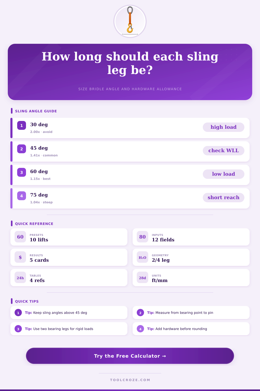
| Sling angle | Angle factor | Per-leg tension with 2 legs | Planning note |
|---|---|---|---|
| 30 deg | 2.000 | 100% of load per bearing leg | Avoid unless specified by a qualified rigging plan |
| 45 deg | 1.414 | 70.7% of load per bearing leg | Common lower boundary for many shop lifts |
| 60 deg | 1.155 | 57.7% of load per bearing leg | Good balance of hook height and sling tension |
| 75 deg | 1.035 | 51.8% of load per bearing leg | Steep angle with lower tension but higher hook height |
| Hardware item | Allowance basis | Typical input | Use in formula |
|---|---|---|---|
| Bow shackle | Pin to bow bearing offset | 0.5 to 2.5 in | Add once per leg unless both ends need separate offsets |
| Master link | Hook seat to link bearing point | 1 to 4 in | Add to shackle allowance for top connection geometry |
| Thimble eye | Eye length and bend radius | 3 to 12 in | Add as eye length at each sling end |
| Adjuster | Take-up or shortening hook travel | 5 to 20% | Use as adjustment factor after allowances |
| Preset geometry | Legs | Typical spacing | Common check |
|---|---|---|---|
| Machinery skid | 2 | 4 to 8 ft wide | Center of gravity and equal sling tension |
| HVAC unit | 4 | 4 x 6 ft to 6 x 10 ft | Corner lug rating and spreader clearance |
| Steel plate | 4 | 6 x 12 ft typical | Plate flex and two-leg load share assumption |
| Pipe bundle | 2 | 6 to 12 ft span | Choke angle, basket cradle, and bundle control |
| Specification check | Where to verify | Why it matters | Calculator input affected |
|---|---|---|---|
| Sling tag WLL | Rated tag or cert | Leg tension changes with angle | Load weight and active legs |
| Pad eye rating | Drawing or lift plan | Pick point may govern the lift | Spacing and lower bearing height |
| Shackle WLL | Body marking and pin size | Side loading reduces usable rating | Hardware allowance and angle |
| Hook capacity | Crane chart and block | Hook height and capacity change by setup | Hook height and clearance |
🗂️ Sling Hardware and Spec Grid
💡 Tips
This calculator estimates bridle sling leg length from lift geometry, angle, hardware, eye allowance, and clearance so riggers can compare practical lengths before final rated lift verification.
When you plan to perform a lift with a bridle sling, you must consider the length of the sling. The length of the sling will determine the angle of the lift. The angle of the lift will determine the tension of the bridle sling.
The tension of the bridle sling will determine whether or not the hardware that you own will work for the lift that you plan to perform. If you choose the incorrect length for the sling, the angle of the lift will change. If the angle of the lift changes, the tension of the bridle sling will change.
How to Measure Bridle Sling Length
If you choose the correct length for the sling, the lift should remain predictable. Many people make mistakes when planning lifts with bridle slings. People often dont measure the proper dimension for the lift.
For example, people may measure the distance between the pick points for the lift. However, they may not account for the hardware between the sling eye and the bearing surface of the load. Additionally, people may not account for the length of the eye of the sling.
Finally, people may not account for any adjustment that may need to be made to the slings once the load is in the air. These type of error tend to make the bridle too short for the load. The geometry for a bridle sling is straightforward.
For a two-leg bridle, half the distance between the pick points will be the length of each leg of the bridle. For a four-leg bridle, the distance from the center of the load to each corner will be half the length of each leg of the bridle. A rigger will combine each of these lengths with the vertical distance from the hook to the load to determine the length of each leg of the bridle.
A calculator can help riggers to perform these type of calculations. A correct understanding of the relationship between the dimensions of a bridle sling and the length of each leg of the sling is required to perform the calculations correctly. Commonly, people make errors in measuring the height of the hook above the floor.
For example, people may measure from the bottom of the hook to the floor. However, the distance that should be measured is from the bearing point of the master link or shackle to the floor. Additionally, the height of the load may need to be taken into consideration.
For example, the pick point of the load may sit on a pad eye on the load that is several inch above the floor. The hook height and the load height are measured separately because they perform different function during a lift. The angle of the bridle sling is important in that the angle will affect the tension of the sling.
If the angle of the bridle sling is below thirty degrees, the tension will be high. If the angle of the bridle sling is between forty-five and sixty degrees, the tension will be within a reasonable range. If the angle created by the sling is steeper than sixty degrees, then more clearance will be required for the lift than many lifting shop may have available.
A reference table can help riggers understand the relationship between the angle of the bridle sling and the tension of each leg of the bridle. Additionally, a calculator can also help riggers to understand these relationships. A hardware allowance must also be made for the sling.
For instance, the pin of a shackle sits within the eye of the sling, but the bearing surface of the shackle sits outside the eye. Therefore, the distance between the shackle pin and the shackle bow must be accounted for in the length of the bridle sling. Additionally, the length of the eye of the sling must also be accounted for in the total length that is needed.
Whether the eye is made of sewn eye, spliced eye, or thimble materials, the length of the eye takes up space within the sling that isnt accounted for in the calculations of the length of each leg of the bridle. These measurements should of been accounted for prior to rounding the numbers that the bridle sling calculator calculates. Four-leg bridles require some additional judgment by the rigging teams.
When performing a lift with a rigid load, the load rarely allows for even distribution of the weight to each leg of the four-leg bridle. Additionally, four-leg bridles are often calculated as if they are two-leg bridles that has four slings attached to the load. The calculator allows the rig team to choose the number of active legs of the bridle sling.
By choosing the number of active legs, the rig team can determine if the teams current bridle slings will be able to handle the lift or if they will need to order new slings. Clearance for the load often gets forgotten by many rigging teams until they attempt to perform the lift. The hook of the crane must have enough clearance above the load to allow the bridle sling to reach the angle that the bridle sling calculator calculates.
If the available rise for the crane hook is only slightly higher than the required clearance for the load, then even the slightest change in the hook angle will cause the bridle sling to fall short of the load. The cranes and rig team calculator will show available clearance. Using this number, the rig team can determine if they have enough clearance to safely perform the lift.
Many lift plans often differ from the ideal scenario that are illustrated in rigging handbooks. For example, the load’s center of gravity may be even. Additionally, the crane hook may not be directly above the pick point of the load.
Finally, the floor on which the load is to be lifted may be sloped. These variables are not accounted for in the cranes and rig team calculation software because they are variables that are accounted for in the lift plan. However, the calculations will allow rig teams to determine the theoretical length of each leg of the bridle sling and the theoretical angle of the sling.
By knowing these theoretical numbers, the rig team can easily determine how much room for error there will be in the lift. An adjustment factor can be added to each calculation to account for these unexpected variables in the actual lift. For instance, adding ten percent to the calculated length will allow for the differences between the theoretical length of the leg of the bridle sling and the actual length that the bridle will be once the hardware is installed to the load.
While some rig teams may require this percentage as an adjustment, other teams may not. However, most rig teams will either perform the calculation or the addition of the ten percent as an adjustment to their calculated length of the bridle sling. The type of bridle sling that is to be used for the lift may have an impact upon the length calculations for the slings.
For instance, round slings are often forgiving of odd surfaces for the load, but they often require protection at the edges of the load. Additionally, wire rope bridle slings are able to hold their length during a lift, but they require that the thimbles and the ropes is inspected prior to lifting. Finally, chain slings are adjustable, but they may add to the weight of the slings that are required for the lift.
The length calculation is the same for all types of bridle slings, but the difference in each sling will impact the decision by the rig team of what type of sling to order for the lift. The purpose of calculating the length of a bridle sling is not to find one specific number for the length of each leg of the bridle. Instead, the rigging team should calculate the length of the bridle sling in a way that allows them to compare the numbers to determine the best option for purchasing the hardware for the lift.