Winch Drum Torque Calculator
Estimate drum torque, motor torque, brake holding torque, layer radius, rope capacity per layer, and reserve margin for workshop winches, trailers, recovery rigs, and small hoists.
🏷 Topic Labels
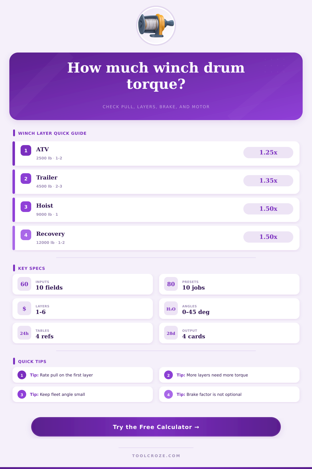
📌 Real Winch Presets
Load a realistic setup, then adjust the pull, rope, drum, gear, brake, and safety values for your own machine.
⚙ Winch Inputs
Calculated Winch Torque
Formula Breakdown
📊 Drum Layer Reference
| Layer | Radius Change | Torque Effect | Practical Note |
|---|---|---|---|
| Layer 1 | Core + 0.5 rope | Lowest torque | Rated line pull is often stated here |
| Layer 2 | Core + 1.5 rope | Moderate rise | Common trailer working layer |
| Layer 3 | Core + 2.5 rope | Noticeable rise | Check motor reserve carefully |
| Layer 4+ | Core + more rope | High torque demand | Pull rating drops as rope stacks out |
The effective radius model assumes the rope seats close to round and the active pull leaves the outer surface of the selected layer.
🔗 Rope Wraps and Capacity Reference
| Rope Diameter | Typical Winch Class | Wrap Behavior | Torque Watchout |
|---|---|---|---|
| 3/16 in or 5 mm | ATV and light utility | Many wraps on narrow drums | Small rope can build layers quickly |
| 5/16 in or 8 mm | UTV and trailer winches | Balanced wrap count | Layer 3 can be a real torque jump |
| 3/8 in or 10 mm | Vehicle recovery | Fewer wraps per layer | Outer layers reduce pulling advantage |
| 1/2 in or 13 mm | Industrial or hoist drum | Large pitch and high load | Check flange and brake capacity |
🛠 Gear and Brake Reference
| Drive Type | Efficiency Range | Brake Factor | Use Case |
|---|---|---|---|
| Worm reduction | 45% to 70% | 1.50x to 2.00x | Self-locking tendency varies by angle |
| Planetary winch | 70% to 85% | 1.50x to 1.75x | Common electric recovery winch |
| Spur/helical box | 80% to 92% | 1.25x to 1.75x | Shop drums and compact machinery |
| Hoist duty drive | 70% to 90% | 2.00x or more | Requires rated hoist components |
📐 Load Angle and Margin Reference
| Angle | Angle Factor | Planning Margin | Field Note |
|---|---|---|---|
| 0 deg | 1.00x | Baseline | Straight line pull |
| 10 deg | 1.02x | Small correction | Good fleet angle target |
| 20 deg | 1.06x | Check side load | Watch spooling quality |
| 30 deg | 1.15x | High correction | Avoid unless rigging is rated |
🗂 Drum, Rope, and Brake Spec Grid
💡 Tips
This calculator estimates winch torque from line pull, drum layer, rope size, gearing, brake factor, load angle, and safety margin for practical workshop planning.
Winches can rotate to lift a load or to drag a vehicle out of mud. However, there is more to the winch than rotation. As the load of rope move outward on the winch drum, the radius of the winch drum increases.
This increase in radius increase the amount of torque that the motor must provide to the winch drum. The motor torque is not a fixed number; it increases with every layer of rope added to the winch. Additionally, the brake on the winch must be able to hold the weight of the load plus any additional loads created by the incline of the road.
How Rope Layers Change Winch Torque
A winch drum torque calculator can help to determine the line pull, the active layer of the winch, the gear efficiency, and the brake factor of the winch. These variables can be tested in a winch drum torque calculator prior to buying the winch hardware required for the job. Many people looks at the winch rating for the winch.
Often, people measure the winch rating at the first layer of rope on the bare winch drum. As winches often develops a load of rope on the drum, the radius of the drum increases. This relationship between the radius of the winch and the load of the vehicle creates an increase in the amount of effort that the motor must exert to move the load.
The difference in radius between the first and third layer of rope, for instance, may be great enough that the torque at each layer must be calculated. To calculate the winch requirements for a specific application, the user must enter the diameter of the bare winch drum, the size of the rope, and the active layer of the winch into the calculator. These fields will return the running torque that the winch drum must exert, the motor torque required to create that winch drum torque, and the torque that the brake on the winch must exert to hold the static load of the winch.
These three quantities will allow a user to determine whether the existing winch drive for the winch can handle the task that is required of the winch. Each of the fields that require an input into the winch torque calculator have some significance to the winch. The diameter of the rope that is used will impact both how fast the winch build up layers of rope and how many wraps can be made by that rope across the winch.
Gear efficiency impacts the amount of motor torque that is lost before it reaches the winch drum. The angle of the load is another factor; a fleet angle will multiply the amount of force applied to the load. Finally, the brake factor impacts the winch; the factor accounts for the difference in the torque that is required to move a load versus to hold it in place when it has stopped.
The tables included within the calculator are based off the conditions of the winch when it is new and there is no load of rope on the winch drum. As discussed above, winches tend to develop a load of rope on the second or third layer of a winch because the winch drum is sized for the total load that the winch should be able to handle. Additionally, the type of rope that is used on recovery vehicles may not be the same as the rope used on winches in a shop.
Therefore, there is an allowance for the type of rope that is to be used in the calculation of the winch requirements. Additionally, shop winches and overhead cranes often experience longer duty cycles than a winch that is used in recovery operations. Therefore, the brake that is used on a shop winch or overhead crane must hold the load for longer periods of time than a recovery winch.
The fields for the brake factor and the safety margin allow users to enter the duty cycle of the winch and create estimates of the motor torque that must be provided to the winch within the duty cycle to create the required line pull. The reference tables included with the calculator are helpful in understanding each of the variables that impact the winch. However, the tables are not to be used for precise calculations of the requirements of the winch.
Each table illustrates the relationship between the radius of the winch drum and the number of layers of rope; the relationship of the diameter of the rope to the number of wraps of the rope; the efficiency of the drive systems for the winch; the angle of the load of the winch; and the relationship of each variable to the winch rating. These tables are not a replacement for the engineering of the winch and the winch system, but they do allow the winch operator to understand each of the variables that may cause problems with the winch that is being used. Common mistakes with winches include treating the winch rating of the winch as a constant value, and ignoring the brake on the winch.
For instance, a winch that is rated for nine thousand pounds of line pull at the first layer may only be able to provide six thousand pounds of line pull at the third layer of rope; the motor that is used for the winch cannot change. If the brake on the winch is sized for the six thousand pound load, the brake will slip when attempting to hold that load. Additionally, another common mistake is to allow the rope to rest against the flange of the winch drum; the winch drum calculations assume that the rope is properly seated on the active layer of the winch such that the load is distributed evenly across the diameter of the drum; it does not take into account the load that can be placed against the flange.
The safety margin field is used to account for the difference between the calculations and the actual performance of the winch. Factors like the seating of the rope, and the viscosity of the oil in the winch gears with temperature can impact the line pull of the winch. Additionally, any load that is placed on the winch that is on an incline will create a component of weight that is not accounted for by the line pull calculations.
Increasing the safety margin allows for adjustments to the calculations to account for these factors. However, increasing the safety margin does not increase the strength of the winch; it only allows the winch operator to understand how much additional motor torque should of been provided to the winch so that the winch will function under non-perfect conditions. In addition to the calculations provided by the calculator, a number of factor exist after the calculation is performed.
For instance, the components that will be used to pull the load must be able to handle the side load created by the winch. Additionally, the frame of the vehicle should be able to handle the torque that the winch will create; it should not twist while the winch is in operation. Finally, the winch should have an anchor point that is designed for the actual force that will be placed upon that winch component.
Although the winch torque calculator will calculate the torque that the winch drum will need to exert, it will not size the remainder of the winch system. Thus, the calculations are only to be used for planning the winch and winch system. The difference between a winch that is successfully completes a job and one that stalls or slips is often the result of the torque on the working layer of the winch.
The first layer of a winch is easily measured; the working layer is not. Therefore, it is helpful to calculate the torque for the winch on both the first and working layer of the winch.