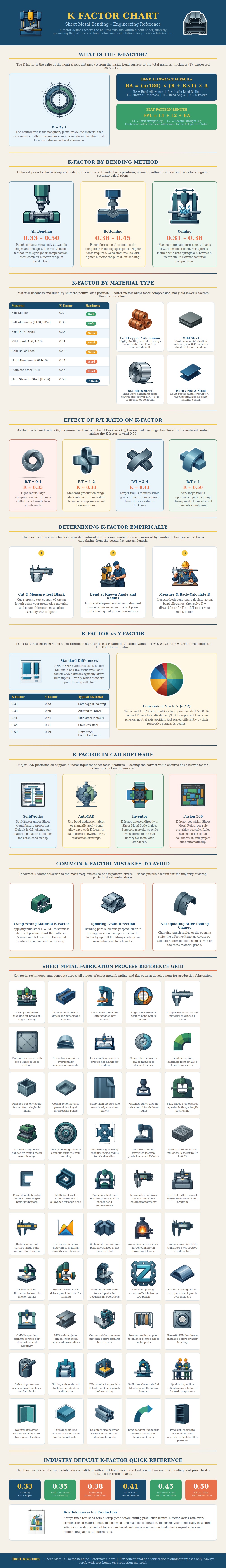
The K-factor is a numerical value that relate to the sheet metal bending process; the K-factor determines the location of an neutral axis within the material. When sheet metal are bent, the inside surface of the metal is compressed, and the outside of the metal is stretch. Within the metal, though, there is a plane in the middle of the sheet that is neither compressed nor stretch.
This plane is known as the neutral axis. The K-factor is represented as a ratio of the thickness of the metal to the distance of the neutral axis from one edge of the metal, and is used to calculate the length of the flat metal blank that should be cut prior to bending. Using an incorrect K-factor will lead to the finished metal part having incorrect dimension; the part will be either too short or too long.
K-factor in Sheet Metal Bending
The location of the neutral axis can change with the type of bending that is perform; therefore, the K-factor will change for each of these bending method. For example, if air bending technique are used, the neutral axis will be further from the inside surface of the metal than if bottoming or coining method are used. Therefore, each metal bending method will require a different K-factor value in it’s calculation.
The property of the metal will also affect the location of the neutral axis; metals with different property will impact the K-factor. Metals that are softer, like copper or 1100 aluminum, will allow the neutral axis to be closer to the center of the metal thickness than metals that are more resistant to compression, like 6061-T6 or 304 stainless steel. Using a K-factor intended for mild steel for stainless steel will result in a part that is too short for the specified dimension.
The radius of the bend will also impact the location of the neutral axis. If the radius of the bend relative to the thickness of the metal is very tight, the neutral axis will shift towards the inside of the metal. A larger radius will shift the neutral axis towards the center of the metal sheet.
Consequently, tighter radii will require K-factor value that are lower than those with larger radii. The K-factor can be treated as a simple value that can be obtained from a chart that relates various metal and metal thickness to their K-factors. However, the K-factor can also be treated as a measured value to improve the accuracy of the sheet metal part that is create.
To measure the K-factor, a person should cut a test strip of the metal to be used, bent at the radius and angle that is to be use in the fabrication of the metal part, and the length of the leg of the bend should be measured. Using these measurement, the K-factor for that specific metal, tooling, and machine can be calculate. This measurement is more accurate than the value from the chart.
Some drawing will use the Y-factor in place of the K-factor; these two factor represent the same value. The Y-factor is represented by the K-factor multiplied by pi divided by two. When using software that require the K-factor but the drawing use the Y-factor, the Y-factor must be converted to the K-factor.
Even with the K-factor being correct for the calculation, there are various reason that the result may still be incorrect. Bending the metal against or with the grain of the metal will alter the K-factor. As the tool wear with extensive metal fabrication, the radius of the inside of the metal may change, altering the K-factor.
Finally, if the thickness of the metal is change without adjusting the K-factor for that thickness of metal, the dimension of the metal part will be incorrect. If the K-factor is measured for various metal and process, the amount of scrap metal can be reduced, as well as the number of delay in delivering the fabricated sheet metal part to the ordered customer. It would of helped to check the machines size first.
