This was not the first time I opened a battery up, as a curious guy who wants to know everything I have opened my old dead batteries like the Ryobi, Milwaukee, Makita and this time the Hilti B22 battery.
As a DIY enthusiast I love understanding how things work, especially these power tools batteries to fix them in the future and mod them to my needs.
I have more than 10 battery packs that I use to create stuff out of and knowing what each pin does is important to me while making changes.
By the way, I also made a short YouTube video about this topic and you can watch it below.
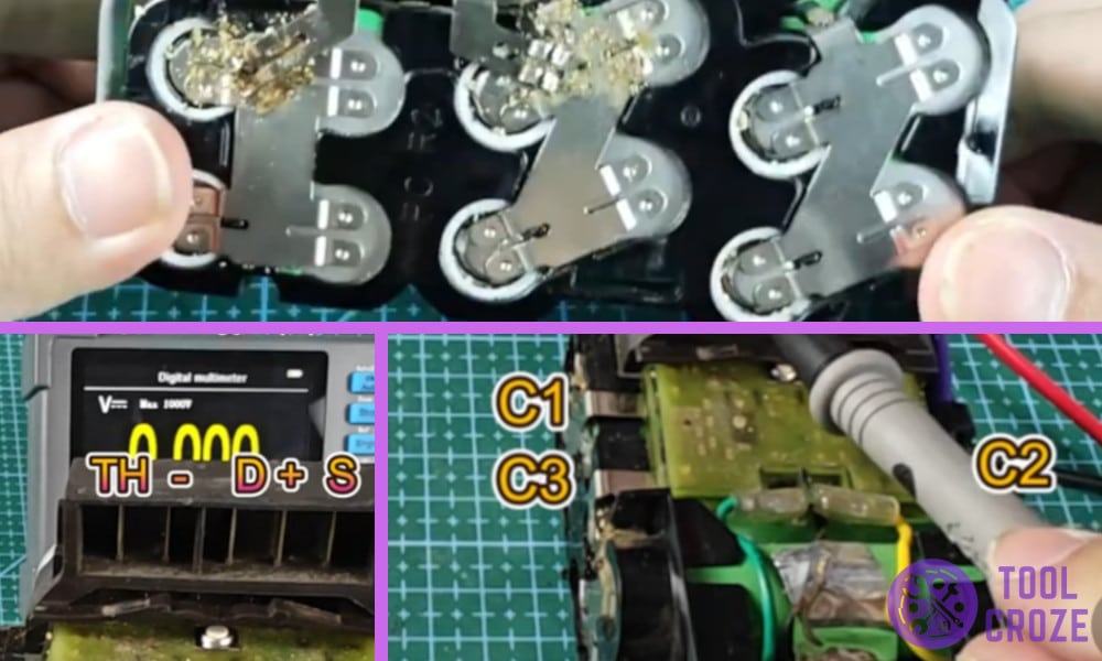
In summary, the Hilti B22 battery has 5 pins, namely TH (Temperature), Negative, D (Data), Positive, and S (Sense). It also has 5 additional contact points which I named as C1, C2, C3, C4 and C5.
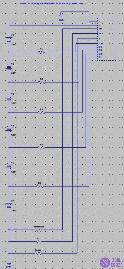
Pinout Wiring Diagram of a Hilti B22 Battery
So this is what I did with my Hilti B22 battery as I opened it up and grabbed my multimeter to test things out. This is everything that I found out converted into a pinout diagram.
I started with collecting the important tools, a multimeter that would help me test the voltages across the pins and some prying tools to open the battery up.
My Hilti battery was always losing its power over time and would only last me 20 minutes or so before losing all of its power and shutting down on me.
I also spent most of the time in the back of the garage so it became the perfect battery for me to test and create a pinout diagram out of.
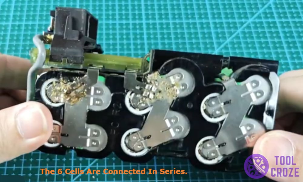
To begin I first removed the sticker from the bottom of the battery which revealed certain screws.
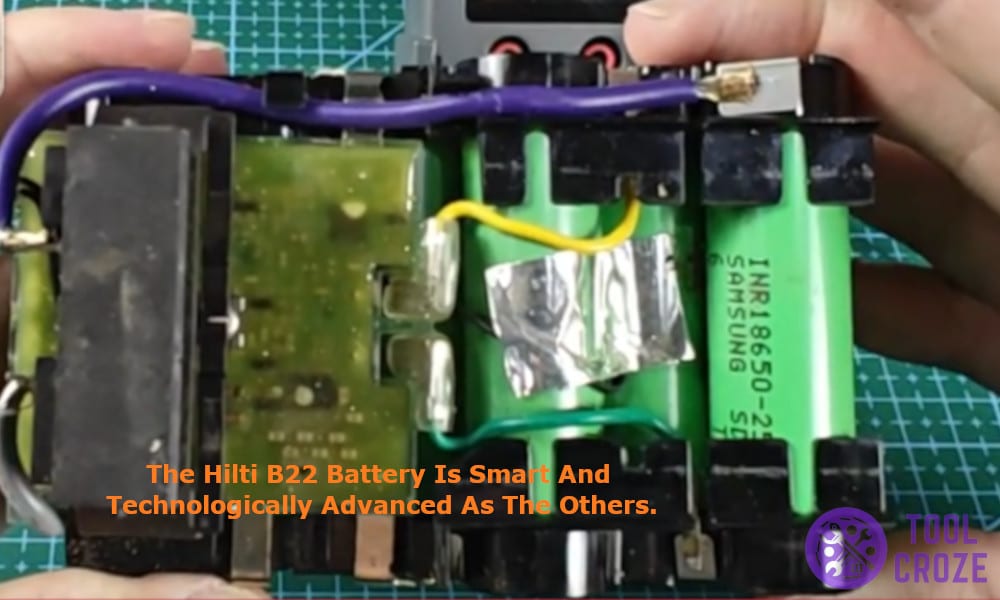
I removed those screws and removed the plastic shielding of the battery only to be left with the circuit and the 6 cells connected in series, these cells were rated at 3.7V and made a total of 21V out of the battery.
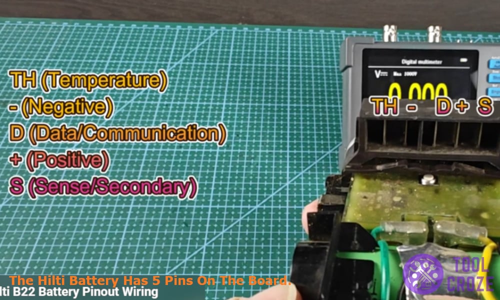
Unlike the most of the batteries that I have tested, the Hilti battery had five pins on the board, which made it a little complex battery compared to other one’s.
This means that the Hilti battery is not to be played with and you need to be cautious when fixing it or modding it.
The five pins that I found I labeled them as Thermistor(TH) the pin responsible for monitoring temperature and trigger the safety feature or the hot and cold delay, Negative(-), Positive(+), Data(D) the pin that contacts with the battery and other communications and lastly the Sense(S) often used by smart chargers to check voltage.
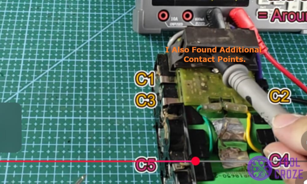
I also found additional contact points which I named as C1, C2, C3, C4 in the diagram to refer to them.
These pins are used to smartly track the internal voltage of the battery and used for balanced charging which is a way for smart chargers to tap into different points and make sure the battery is healthy and is charging normally.
Then it was time for the real test, to check the readings of the battery from each combination of the points.
- Positive – Negative – 21.6V
- Negative – TH – 0V
- Positive – TH – 21.6V
- Negative – D – 0V
- Positive – D – 21.6V
- Negative – S – 0V
- Positive – S – 21.6V
- Negative – C1 – 3.6V
- Negative – C2 – 7.2V
- Negative – C3 – 10.8V
- Negative – C4 – 14.4V
- Negative – C5 – 18V
While the Hilti B22 battery might be as common as the other batteries, it’s just as smart and technologically advanced as the other.
It has extra data pins to smartly monitor the internal voltage and the safety feature pin such as the hot and cold delay thermistor pin to keep the battery safe. Once you understand the layout, it’s easy to test, repair and build around.
